EPSON Stylus COLOR 760
Revision C
Adjustment
Adjustment
123
5.2.3.6 Head Angular Adjustment
During production, slight variations are created in printheads and
carriage (which are used as a printhead base.) If these differences are
not adjusted, they can adversely influence the printhead angle, and
color overlapping is not performed correctly and color/white line
problem occurs as a result. Therefore, in order to adjust the printhead
angle correctly, the exclusive lever for adjusting the printhead angle is
installed on the side of the carriage unit. By moving this lever, you are
able to adjust the printhead angle without removing the ink cartridge.
This adjustment is required in the following cases.
n
When the printhead is replaced
n
When the carriage unit is replaced.
n
When the angle adjustment lever is moved.
Print the check pattern in the adjustment program to determine the
angle degree needed for the printhead. Then move the adjustment lever
in the carriage unit to set the printhead angle referring to the printed
check pattern.
1.
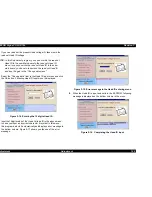
Select the “Head angular adjustment” in the Adjustment Main Menu
as following figure.
Figure 5-17. Select the Head angular adjustment
2.
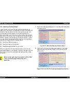
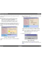
Select the “Print head angular adjustment pattern” in the “Head
angular adjustment menu and click the “OK” button to print the
check pattern.
Figure 5-18. Select the Print head angular adjustment pattern
C A U T I O N
Before or after performing this operation, refer to Table
5-2 and perform appropriate adjustments or
operations.
Содержание Stylus Color 760
Страница 1: ...EPSONStylusCOLOR760 Color ink jet printer SEIJ99004 SERVICE MANUAL ...
Страница 8: ...C H A P T E R PRODUCTDESCRIPTION ...
Страница 27: ...C H A P T E R OPERATINGPRINCIPLES ...
Страница 53: ...C H A P T E R TROUBLESHOOTING ...
Страница 72: ...C H A P T E R DISASSEMBLYANDASSEMBLY ...
Страница 109: ...C H A P T E R ADJUSTMENT ...
Страница 142: ...C H A P T E R MAINTENANCE ...
Страница 152: ...APPENDIX C H A P T E R ...
Страница 163: ...PSON Stylus COLOR 760 Revision C ppendix Circuit Board Component Layouts 163 Figure 7 5 C298PNL Component Layout ...


