CHAPTER 3 Disassembly and Assembly
Table of Contents
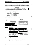
3.1 OVERVIEW
3-1
3.1.1 Disassembly Precautions . . . . . . . . . . . . . . . . . . . . . . . . . . . . . . . . . . . .
3.1.2
. . . . . . . . . . . . . . . . . . . . . . . . . . . . . . . . . . . . . . . . . ........0-.
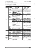
3.1.3 Service ChecksAfterRepair . . . . . . . . . . . . . . . . . . . . . . . . . . . . . . . . . . 3-2
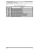
3.1.4 Specifications
. . . . . . . . . . . . . . . . . . . . . . . . . . . . . . . . . . . . 3-3
3.2 DISASSEMBLY AND ASSEMBLY
3-4
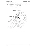
3.2.1 Removing the Printhead . . . . . . . . . . . . . . . . . . . . . . . . . . . . . . . . . . . . . 3-5
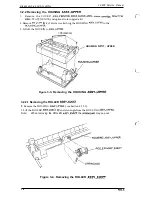
3.2.2 Removing the
HOUSING
. . . . . . . . . . . . . . . . . . . . . . . .
3-6
3.2.2.1 Removing the ROLLER
ASSY.,EJECT. . . . . . . . . . . . . . . . . . . .
3-6
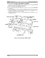
3.2.3 Removing the BOARD
and
. . . . . . . . . . . . . . . . 3-7
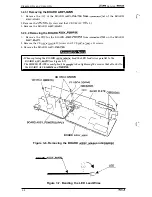
3.2.3.1 Removing the BOARD
. . . . . . . . . . . . . . . . . . . . .
3-8
3.2.3.2 Removing the BOARD
. . . . . . . . . . . . . . . . . . 3-8
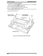
3.2.4 Removing the Printer Mechanism . . . . . . . . . . . . . . . . . . . . . . . . . . . . . . 3-9
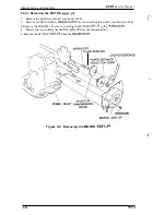
3.2.4.1 Removing the MOTOR ASSY.,PF . . . . . . . . . . . . . . . . . . . . . . 3-10
3.2.4.2 Removing the MOTOR
. . . . . . . . . . . . . . . . . . . . . . 3-11
3.2.4.3 Removing the PLATEN. . . . . . . . . . . . . . . . . . . . . . . . . . . . . . . 3-12
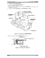
3.2.4.4 Removing the DETECTOR,PE. . . . . . . . . . . . . . . . . . . . . . . . . 3-13
3.2.4.5 Removing the DETECTOR, HP. . . . . . . . . . . . . . . . . . . . . . . . . 3-14
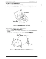
3.2.4.6 Removing the Release
Lever Position Sensor . . . . . . . . . . . . .
3-14
3.2.4.7 Removing the CARRIAGE ASSY.. . . . . . . . . . . . . . . . . . . . . . . 3-15
3.2.4.8 Removing the Ribbon Drive Gear Assembly. . . . . . . . . . . . . . . 3-16
3.2.4.9 Removing the PF Gear Assembly. . . . . . . . . . . . . . . . . . . . . . . 3-16
3.2.5 Removing the BOARD ASSY.,INTERFACE . . . . . . . . . . . . . . . . . . . . . 3-17
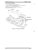
3.2.6 Removing the ROLLER
. . . . . . . . . . . . . . . . . . . . . . . 3-18
3.2.7 Disassembling and Assembling the Optional Color Upgrade Kit. . . . . . 3-19
3.2.7.1 Removing the MOTOR
. . . . . . . . . . . . . . . . . . . . . . 3-19
3.2.7.2 Removing the GEAR,
. . . . . . . . . . . . . . . . . . . . . . . . . 3-19
3.2.7.3 Removing the Color Ribbon Sensor . . . . . . . . . . . . . . . . . . . . . 3-19
Содержание LX-300
Страница 1: ... EPSON TERM NAL PR NTER LX 300 SERVICE MANUAL EPSON ...
Страница 4: ...REVISION SHEET Revision Issue Date Revision Page Rev A April 6 1994 1st issue 4 j v ...
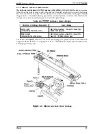
Страница 95: ...Maintenance LX 300 Service Manual k w n M IL f Figure 6 1 LX 300 Lubrication Points 6 2 Rev A ...
Страница 103: ...LX 3 M Samica Manual Appandix A 4 EXPLODED DIAGRAM 0 l T Figure A 7 LMOO Exploded Diagram 1 A 10 Rev A i ...
Страница 104: ...Appendix LX Service Manual Rev A A n ...


