EPSON
LQ-570e/LQ-580
Revision
C
Disassembly
and Assembly
Disassembly
and Assembly
83
4.2.8
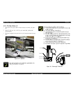
Platen Removal
1.
Remove
the paper guide assembly, top cover, front cover, paper eject cover, knob and
tractor
unit. (See 4.2.1 "Pre-disassembly Procedures".)
2.
Remove
the upper housing. (See 4.2.4 "Upper Housing Assembly Removal".)
3.
Remove
2 CBS (3x8) screws securing the platen cover.
4.
Turn
the lever portion of the left bushing 8 toward the front of the mechanism until the
lever
boss unlock from small window on the left frame assembly.
5.
Slide
the platen to the right until the lever portion of the left bushing 8 passes inside the
left
frame, and take it off upward.
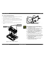
Figure
4-14. Platen Removal
Platen
Assy
Platen
Cover
Frame
Assy, Left
Bushing
8, Left
Paper
Guide Assy Support; B
n
Be
careful not to damage on the paper guide support; B.
n
No
gap between the platen assembly and the paper guide
assembly
support; B.
A D J U S T M E N T
R E Q U I R E D
After
replacing the platen, perform the parallel adjustment.
(See
“Parallel Adjustment” on page 95.)
Содержание LQ-570e
Страница 8: ...C H A P T E R 1 PRODUCT DESCRIPTION ...
Страница 46: ...C H A P T E R 2 OPERATINGPRINCIPLES ...
Страница 57: ...C H A P T E R 3 TROUBLESHOOTING ...
Страница 70: ...C H A P T E R 4 DISASSEMBLYANDASSEMBLY ...
Страница 93: ...C H A P T E R 5 ADJUSTMENT ...
Страница 101: ...C H A P T E R 6 MAINTENANCE ...
Страница 106: ...C H A P T E R 7 APPENDIX ...
Страница 119: ...EPSON LQ 570e LQ 580 Revision C Appendix Components Layout 119 Figure 7 3 C293PSB Component Layout ...
Страница 120: ...EPSON LQ 570e LQ 580 Revision C Appendix Components Layout 120 Figure 7 4 C293PSE Component Layout ...
Страница 127: ......
Страница 128: ......
Страница 129: ......


