


EPSON
LQ-570e/LQ-580
Revision
C
Troubleshooting
Repairing
the Printer Mechanism
68
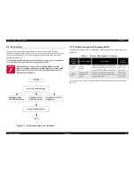
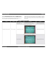
3.5
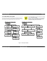
Repairing the Printer Mechanism
For
detailed procedures for replacing or adjusting matter, refer to Chapter 4, Disassembly
and
Assembly and Chapter 5, adjustments. If a problem or symptom occurs, refer to
following
tables to try find other potential causes.
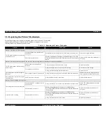
Table
3-3. Repairing the Printer Mechanism
Symptom
Cause
Check
point
Solution
Problem:
The CR motor fails to operate.
The
CR motor fails to drive the timing
belt
after power on.
Foreign
substances are lodged in the
mechanism.
Manually
move the timing belt to see if the motor can rotate freely.
Remove
the foreign substance.
The
CR motor is defective.
Measure
the motor coil resistance. It should be about 2.7
Ω
±
10%.
If
the coil is shorted, also verify CR motor driver IC9 on the main
board.
Replace
the CR motor (and main board, if
necessary).
Problem:
The carriage dose not operate when power on (after carriage has been centered prior to power on manually).
The
CR motor rotates, but the carriage
dose
not move.
The
belt drive or driven pulley is
defective.
Verify
the pulleys which are broken or worn.
Replace
the pulleys.
The
timing belt is defective.
Verify
the timing belt is set correctly to the carriage.
Reset
the belt to the carriage.
Verify
whether the timing belt is broken or not.
Replace
the belt.
The
carriage moves to the left slightly,
then
stops.
The
carriage movement is not smooth.
Verify
whether the carriage moves smoothly when move manually.
lean
and lubricate the CR guide shaft or
frame.
Otherwise, replace the CR motor.
The
carriage moves to the left or right
end,
then stops.
The
HP detector is defective.
Verify
the HP detector by multi meter.
Replace
the HP detector.
Problem:
Self test printing is not executed.
The
carriage moves, but does not print.
The
printhead FFC common wires are
disconnected.
Verify
whether FFC is set or not to the printhead or the main board.
Set
the FFC to the printhead or the main
board
correctly.
The
printhead is defective.
Measure
the printhead coil resistance. It should be about
29.6
±
3.0
Ω
.
If the printhead is shorted, also verify the drivers on
the
main board.
Replace
the printhead, (and drivers, if
necessary).
A
particular dot is missing.
The
printhead is defective.
Measure
the printhead coil resistance. It should be about
29.6
±
3.0
Ω
.
If the printhead is shorted, also verify the drivers on
the
main board.
Replace
the printhead, (and drivers, if
necessary).
Verify
whether head wire is born or not.
Replace
the printhead.
Содержание LQ-570e
Страница 8: ...C H A P T E R 1 PRODUCT DESCRIPTION ...
Страница 46: ...C H A P T E R 2 OPERATINGPRINCIPLES ...
Страница 57: ...C H A P T E R 3 TROUBLESHOOTING ...
Страница 70: ...C H A P T E R 4 DISASSEMBLYANDASSEMBLY ...
Страница 93: ...C H A P T E R 5 ADJUSTMENT ...
Страница 101: ...C H A P T E R 6 MAINTENANCE ...
Страница 106: ...C H A P T E R 7 APPENDIX ...
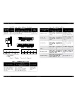
Страница 119: ...EPSON LQ 570e LQ 580 Revision C Appendix Components Layout 119 Figure 7 3 C293PSB Component Layout ...
Страница 120: ...EPSON LQ 570e LQ 580 Revision C Appendix Components Layout 120 Figure 7 4 C293PSE Component Layout ...
Страница 127: ......
Страница 128: ......
Страница 129: ......