background image

EOS Zeus S / EOS Zeus SL - Installation and Operating Instructions

EN-39

Commissioning

3

Lay the stones one by one on the stone grate to create a small pile. En-
sure there is enough space between them. 

Do not place the stones on the decoration ring. The air must flow 
freely.

5.2  

Starting the heater

A slight odour may be produced the first time the cabin is heated because 
the heater is being heated for the first time. The odour ceases upon contin-
ued operation of the heater.

Switching the system on

1

Switch the sauna control unit on.

The heater is switched on via the control unit.

2

Use the control unit to select a suitable program.

5.3  

Commissioning by remote control

If you switch on the heater using the remote control, ensure that no 
objects are placed on the heater. A suitable safety system, for 
example EOSafe D/L, can be used to prevent this. 

Содержание 94 7371 01

Страница 1: ...Druck Nr 2902 4998 Stand 48 20 EN Made in Germany EOS Zeus S EOS Zeus SL Heater for Sauna Cabins Installation and Operating Instructions...

Страница 2: ...risation are not permit ted Compensation will be claimed in the event of infringements All rights reserved with regard to patent claims or submission of design or utility patent Characters symbols and...

Страница 3: ...Technical data EN 14 3 Installation EN 17 3 1 Specifications for the cabin EN 17 3 1 1 Installation site EN 18 3 1 2 Air inlets and outlets EN 19 3 1 3 Connection cable EN 22 3 2 Temperature sensor EN...

Страница 4: ...5 2 Starting the heater EN 39 5 3 Commissioning by remote control EN 39 5 4 Water splash EN 40 6 Maintenance EN 41 6 1 Cleaning the heater EN 41 6 2 Replacing sauna stones EN 42 6 3 Replacing the tubu...

Страница 5: ...are classified Please familiarise yourself with the following terms and symbols WARNING Warning Indicates a hazardous situation which if not avoided could result in death or serious injury CAUTION Ca...

Страница 6: ...ction This risk also applies follow ing completion of the installation work The electrical installation of the heater relay boxes and other electrical systems or equipment with a fixed mains connectio...

Страница 7: ...bin may reach a maximum tem perature of 76 C Appropriate protection may need to be installed if required Risk of burns from hot unit During operation the sauna heater may become hot and if touched cou...

Страница 8: ...lways installed in the lower part of the wall diagonal to the sauna heater The supply and exhaust openings must not be closed Please observe the instructions provided by your sauna cabin manufacturer...

Страница 9: ...by a trained specialist The system must be disconnected and removed entirely from the mains supply before commencing repair work Use only original spare parts from the manufacturer Fire hazard Object...

Страница 10: ...eave the room unconsciousness Alcohol drugs and medications increase the risk of hyperthermia Do not exceed the maximum recommended time in the sauna Leave the sauna cabin if your body responds abnorm...

Страница 11: ...The heater is operated with one of the following control units Econ series EmoTec series EmoStyle series EmoTouch series The control unit is not included in the scope of delivery An output controller...

Страница 12: ...proper working order Contact your distributor if components are missing or damaged The unit must not be operated if components are missing or damaged The following parts are included in the scope of...

Страница 13: ...mbient air as well as other weather condi tions Any use beyond this is considered improper use Proper use also includes compliance with operating maintenance and servicing requirements The manufacture...

Страница 14: ...0 C in the cabin along the floor Therefore it is not unusual that if the tem perature sensor above the heater reads 110 C the thermometer that is mounted approx 20 25 cm below the cabin ceiling on the...

Страница 15: ...onnection control unit output controller 6 0 kW 5 x 2 5 mm2 5 x 1 5 mm2 7 5 kW 9 0 kW 10 5 kW 5 x 2 5 mm2 5 x 1 5 mm2 4 x 1 5 mm2 12 kW Heater output Fuse protection for control unit Fuse Output contr...

Страница 16: ...eater output Cabin volume Minimum size of air inlet and outlet Output controller LSG Control system 6 0 kW 6 8 m3 35 x 5 cm 18 cm Econ series EmoTec series EmoStyle series EmoTouch series 7 5 kW 7 10...

Страница 17: ...tions The heater is not designed to be installed or set up in an alcove or under a bench or sloping roof 3 1 Specifications for the cabin The cabin must be planned and installed according to specifica...

Страница 18: ...be observed Ceiling height min 1900 mm Distance between heater and cabin ceiling at least 1200 mm Distance between heater and cabin wall at least 80 mm Distance between heater guard rail and bench at...

Страница 19: ...a fan if necessary Commission the cabin only after all air inlets and outlets have been opened If the heating process takes a long time the underlying reason is that the heater receives insufficient...

Страница 20: ...sions depending on heater output min 180 mm see 2 5 Technical data EN 14 Installing the air inlet in the cabin floor This form of air supply requires that the slats on the bottom of the heater are ben...

Страница 21: ...r two small openings The air inlet must meet the following criteria Location From the side in relation to the heater at the height of the lower openings A duct directs fresh air to the opening or open...

Страница 22: ...from the installation site of the heater up to the relay box The radius for laying the cable around a corner must equal a minimum of 100 degrees R100 See the connection diagrams in Connections EN 31...

Страница 23: ...is prepared the heater is placed on a pre defined installa tion site Two people should always transport the heater or a lifting device should be used A drip pan is mounted under the heating element It...

Страница 24: ...aterfromthepallet Then move it to the pre defined installation site 2 Unscrew the 3 adjustable feet 25 35 mm until the heater is level Use a spirit level if needed to ensure that the heater is level 3...

Страница 25: ...n such a way that it pro tects sauna guests from making inadvertent contact with the heater During installation Ensure that the heater has no power Allow the heater to cool down Remove all stones Hard...

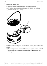
Страница 26: ...tom of the heating element To do this access the screws from above between the heating element and the outer casing 5 Hold the tubular heating elements and lift the heating element from the heater The...

Страница 27: ...EOS Zeus S EOS Zeus SL Installation and Operating Instructions EN 27 Installation The connection cable is looped enough that when the heating element is lifted the cable has enough play...

Страница 28: ...openings for the heater guard rail brackets 2 Insert the 3 hex screws M8 x 40 mm B from the inside into the holes Screw on the screw bushings C from the outside and tighten 3 In the middle of the fron...

Страница 29: ...e outer casing and lower it onto the heater 6 Insert the heater rail with the inner centred pin 6 mm in the bushing of the front bracket 7 Insert the lateral fixing inserts in the pre milled pockets o...

Страница 30: ...y the connection cable looped in an appropriate place b Insert the stone grate and tighten the screws c Position the decoration ring and tighten the screws d Place the stones in the rock store Do not...

Страница 31: ...turer In this case the heater must be heated by a technician under supervision which will bypass the RCD function Once the moisture has escaped from the heating elements after approx 10 minutes the RC...

Страница 32: ...tructions EOS Zeus S EOS Zeus SL EN Connections 4 2 1 Terminal diagram 6 kW 7 5 kW 9 kW A Sauna control unit B Heater sensor with safety temperature limiter C Sauna heater 400 V 3N AC L1 L2 L3 N W V U...

Страница 33: ...ring 6 kW 7 5 kW 9 kW A Sauna control unit B Heater sensor with safety temperature limiter C Sauna heater D Output controller LSG 400 V 3N AC L1 L2 L3 N W V U N 3x16A N U V W N U V W 1 1 1 1 S1 N 400...

Страница 34: ...S Zeus SL EN Connections Internal wiring 10 5 kW Internal wiring 12 kW U V W N 1500W 2000W 1500W 1500W 2000W 2000W V W N U PE Gr Gr PE Control system Output control U V W N Gr PE 2000W 2000W 2000W 200...

Страница 35: ...auna relay box 1 Route the connection cable along the internal side of the heater wall downward 2 Route the connection cable outward The following alternatives are available depending on how the cable...

Страница 36: ...th a timer that complies with IEC and EN standards This timer fully disconnects the sauna heater from the power supply for safety reasons It is typically integrated in the sauna control units The time...

Страница 37: ...tch fire Herbs or similar substances used for aroma infusion pur poses which are located near the heater could catch fire Inspect the cabin prior to each use WARNING Risk of fire due to heating withou...

Страница 38: ...stones when infused Use only natural sauna stones in the prescribed grain size of approx 50 80 mm Filling stones 1 Thoroughly rinse the stones with running water 2 WARNING Stones that are positioned t...

Страница 39: ...ed the first time the cabin is heated because the heater is being heated for the first time The odour ceases upon contin ued operation of the heater Switching the system on 1 Switch the sauna control...

Страница 40: ...o the water than the amount indicated on the container Never use alcohol or pure concentrate Do not add herbs to the water or on the stones Do not use pure sauna essences for water splashes Do not use...

Страница 41: ...sioning no towels cleaners or other objects are lying on the heater Contact your sauna retailer or the manufacturer directly if you notice mal functions or signs of wear and tear 6 1 Cleaning the heat...

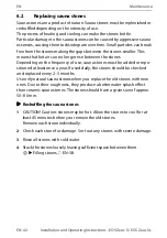
Страница 42: ...Depending on the frequency of use sauna stones must be added or repo sitioned at least once a year If used daily the stones should be checked and replaced every 2 3 months Use only natural sauna ston...

Страница 43: ...g coil EN 43 Replacing the tubular heating elements EN 47 Inserting the heating coil EN 49 Replacing the entire heating coil EN 49 Hardware tools Tubular heating element or heating coil Screwdriver Pl...

Страница 44: ...nd Operating Instructions EOS Zeus S EOS Zeus SL EN Maintenance 3 Remove the stone grate 4 Loosen the 3 screws underneath on the inner casing To do this access the screws from above between the inner...

Страница 45: ...hed Depending on the output capacity the heating element can have up to 6 tubular heating elements 6 Loosen the 8 screws at the bottom of the heating element 4 screws on both the right and left sides...

Страница 46: ...intenance 9 Remove the top and bottom steel plate 10 Remove the heating coil with the terminal box You can now replace the defective tubular heating element or insert a completely new heating coil Rep...

Страница 47: ...r heating elements 1 Remove the heating element See Removing the heating coil EN 43 2 Loosen the 6 screws on the terminal box 3 Identify the defective tubular heating element by taking measurements Th...

Страница 48: ...licone seal and the pressure plate to tighten it in place Check the old silicone seal and reseal as needed The screw must be screwed in tightly so that water cannot seep into the terminal box 7 Attach...

Страница 49: ...tighten the 3 screws 6 Position the decoration ring in place and tighten the 6 screws 7 Place the stones loosely on the stone grate See Reshuffling the sauna stones EN 42 8 Reconnect the power supply...

Страница 50: ...ngs See 3 1 2 Air inlets and outlets EN 19 The heater is very hot but cannot distribute the heat throughout the cabin There is not enough space between the stones Reshuffle the stones See Reshuffling...

Страница 51: ...s terms and conditions included in the customer s General Terms and Conditions of Business or order confirmation Unconditional acceptance of order acknowledge ments or deliveries shall not be constru...

Страница 52: ...arranty shall apply only if installation operation and maintenance have been carried out in full accordance with the manufac turer s specifications in the installation and operating instructions The w...

Страница 53: ...expense Electrical assembly and installation work including service visits and parts replacements shall be carried out at the customer s expense costs shall not be borne by the manufacturer Complaints...

Страница 54: ...ard Plastic foil Electronic waste Electronic waste must be disposed of at the designated local collection point for electronic waste Electrical devices that are no longer needed must be recycled at a...

Страница 55: ...EOS Zeus S EOS Zeus SL Installation and Operating Instructions EN 55...

Страница 56: ...place Please always provide us with nameplate data such as model item num ber and serial number so we can provide fast and efficient support Date of sale Stamp retailer signature EOS Saunatechnik GmbH...

Отзывы: