background image

12 

Call 1300 369 273 

www.enware.com.au

SERVICE & MAINTENANCE

SOLENOID MAINTENANCE
For long periods of non-use, a minimum activation of 

1-2 times per day is recommended.
High frequency of use and high water supply pressures 

reduce the service life of a solenoid.
If the solenoid is not working correctly or leaking, go 

through the following steps to service the solenoid. 

The most common cause of solenoid malfunction is 

debris being caught inside, in which case the solenoid 

needs to be dismantled and cleaned. Service kits 

including replacement diaphragms are available.
To Access the Solenoid Valve
1.  Turn  water  supply  off  and  activate  the  sensor  to 

drain as much water from the fitting as possible. Turn 

power off to the sensor.

2.  In  most  cases  it  is  easier  to  remove  the  solenoid 

valve completely from the installation to service it. 

Remove the electrical connectors from the solenoid 

terminals, undo the water connections on both the 

water inlet and outlet of the solenoid, and remove 

the solenoid. 

3.  The solenoid can be disassembled and checked for 

debris  or  damage  to  the  diaphragm.  Refer  to  the 

instructions below for “Servicing the Solenoid”. Take 

note of the location of the components so that it can 

be reassembled in the correct order. 

4.  Service  or  replace  the  solenoid  and  re-install  into 

the  line.  Push  the  cable  connectors  back  onto  the 

solenoid terminals

5.  Turn power on and test tap.

Servicing the Solenoid

Tools required: Spanner, T20 Torx Bit
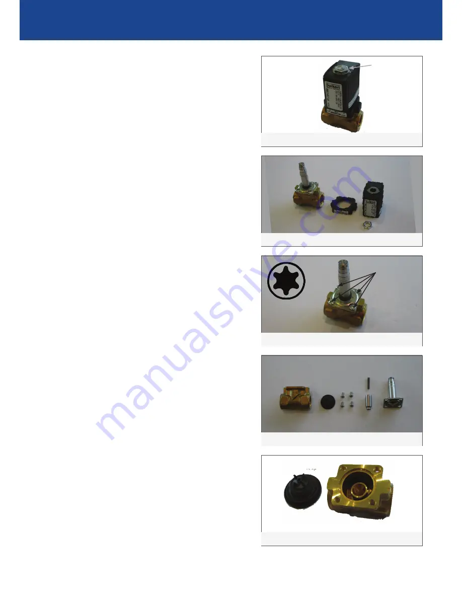
1.  Remove  the  nut  located  on  top  of  the  solenoid. 


SEE IMAGE 8

2.  Remove the black coil body and plastic cover from 

the core tube. SEE IMAGE 9

3.   Using a T20 Torx screw driver (star bit), remove the 

4 Torx screws that are holding the core tube. Use the 

correct size tool and take care not to round the screws 

heads. Keeping in mind that the plunger inside the 

core tube is spring loaded, dismantle the valve with 

care. Take note of the order of parts assembled. SEE 

IMAGES 10, 11, 12

4.  Check seat and diaphragm for debris or any damage. 

SEE IMAGE 12

  57.5

  10

  100

  26

  130

  200
  180

  110

  85

22

  33

  16

  55

  10

5 TYP

DEPTH)

SPACE FOR

CIRCUIT BOARD

(REQUIRES 30mm

COVER PLATE 

OUTLINE

IMAGE 9

  57.5

  10

  100

  26

  130

  200
  180

  110

  85

22

  33

  16

  55

  10

5 TYP

DEPTH)

SPACE FOR

CIRCUIT BOARD

(REQUIRES 30mm

COVER PLATE 

OUTLINE

IMAGE 8

NUT

  57.5

  10

  100

  26

  130

  200
  180

  110

  85

22

  33

  16

  55

  10

5 TYP

DEPTH)

SPACE FOR

CIRCUIT BOARD

(REQUIRES 30mm

COVER PLATE 

OUTLINE

IMAGE 10

T20 TORX

4 X TORX 

(T20) 

SCREWS

  57.5

  10

  100

  26

  130

  200
  180

  110

  85

22

  33

  16

  55

  10

5 TYP

DEPTH)

SPACE FOR

CIRCUIT BOARD

(REQUIRES 30mm

COVER PLATE 

OUTLINE

IMAGE 11

  57.5

  10

  100

  26

  130

  200
  180

  110

  85

22

  33

  16

  55

  10

5 TYP

DEPTH)

SPACE FOR

CIRCUIT BOARD

(REQUIRES 30mm

COVER PLATE 

OUTLINE

IMAGE 12

Содержание ENMATIC 5000 SERIES

Страница 1: ...d with 205mm Spout ENM5072 205 ENM5072 250 Wall Sensor Tap Wave On Wave Off Stainless Steel Sensor Panel Mains powered with 205mm or 250mm Spout ENMATIC 5000 SERIES WALL SENSOR TAP HANDS FREE Call 1300 369 273 www enware com au Enware Australia Pty Limited 9 Endeavour Rd Caringbah NSW 2229 Australia Ph 61 2 8556 4000 Fax 61 2 8556 4055 ...

Страница 2: ... open If the solenoid valve remains open for more than 45 seconds the unit will time out and close the valve automatically This is intended to conserve waterandpreventoverflows Thetime outperiod can be adjusted to 15 30 45 or 60 seconds see appendix Sensor Programs The Enmatic Wall Sensor Tap is a sensor operated hands free tap that is installed onto walls above sinks basins or wash troughs It ope...

Страница 3: ...00 180 110 85 22 33 16 55 10 5 TYP DEPTH SPACE FOR CIRCUIT BOARD REQUIRES 30mm COVER PLATE OUTLINE 59 88 58 2 m LONG CABLE SPADE CONNECTORS TO SOLENOID 3 PIN FEMALE CONNECTOR TO SENSOR 2 m LONG CABLE EMS805 Transformer 57 5 10 100 26 130 200 180 110 85 22 33 16 55 10 5 TYP DEPTH SPACE FOR CIRCUIT BOARD REQUIRES 30mm COVER PLATE OUTLINE 200 130 55 40 50 SENSOR ENM5072 Front View 57 5 10 100 26 130 ...

Страница 4: ...ed water at a maximum of 50 C Enware products are to be installed in accordance with the Plumbing Code of Australia PCA and AS NZS3500 Installations not complying with PCA and AS NZS 3500 may void the product and performance warranty provisions Reference should also be made to the Australasian Health facility Guidelines AHFG ABCB and Local Government regulations when considering the choice of and ...

Страница 5: ...tions and Lighting If the sensor unit is installed into a location where a nearby wall or object is reflecting the Infrared light back the unit is effectively blinded and will not operate Up to 600mm clearance may be necessary from reflective surfaces such as ceramic tiles and stainless steel directly in front of and parallel to the front face of the sensor Any bright lighting reflecting off a hig...

Страница 6: ...mum of 25mm conduit to allow for servicing and replacement in future BEFORE CONNECTING WATER SUPPLY Ensure all supply lines are flushed thoroughly to remove debris prior to the installation of this product Strainers 40 mesh are recommended if debris is an ongoing problem A Pressure reduction valve may be required to comply with the recommended maximum supply pressure and or balanced pressure requi...

Страница 7: ...e position of the sensor is determined fix the sensor mounting bracket inside wall Take note of the maximum and minimum wall depths for the sensor Before the wall is sheeted or finished allow for a cut out in the finished wall surface of 193mm wide x 115mm high rectangular hole Wall Depth Minimum wall depth 65mm maximum 80mm Wall Cut Out Dimensions 193mm wide x 115mm high rectangular hole in wall ...

Страница 8: ...his may be through an access panel on the wall or ceiling The power pack has a 2 metre lead to the sensor and 1 8 metre lead from the sensor to the solenoid Additional lead lengths up to 6 metres can be accommodated with extension cables available separately from Enware Plug the 24V AC power pack into the 240V AC power point WARNING Protecting from Water Spray Note that the power pack and connecti...

Страница 9: ...ting the plate as the tap is now operational and will activate TESTING Turn on the power to the unit and test the unit Wave On Wave Off Model Wave the back of your hand through the beam to turn the water on and again to turn the water off Time Flow Simply place your hand in front of sensor and activate the sensor For more details on sensor functions refer to Sensor Program WARNING Sensor component...

Страница 10: ...Re install valve correctly Debris in solenoid valve Port hole in solenoid diaphragm is blocked Take solenoid apart and clean debris from plunger or diaphragm Solenoid diaphragm is damaged Replace solenoid diaphragm with service kit Warer supply pressure is too low check dynamic water pressure is at least 100 kPa Tap Water turns on by itself Sensor is picking up reflections or movement Relocate sen...

Страница 11: ...malfunctioning the entire sensor plate will need to be replaced REPLACING THE POWERPACK The powerpack is a non serviceable component If damaged the powerpack must be replaced CLEANING Enware Product should be cleaned with a soft damp cloth using only mild liquid detergent or soap and water Do not use cleaning agents containing a corrosive acid scouring agent or solvent chemicals Do not use cream c...

Страница 12: ...orrect order 4 Service or replace the solenoid and re install into the line Push the cable connectors back onto the solenoid terminals 5 Turn power on and test tap Servicing the Solenoid Tools required Spanner T20 Torx Bit 1 Remove the nut located on top of the solenoid SEE IMAGE 8 2 Remove the black coil body and plastic cover from the core tube SEE IMAGE 9 3 Using a T20 Torx screw driver star bi...

Страница 13: ...is is done place the core tube back on top of the valve and tighten back up with the 4 Torx screws 10 Once the core tube is tightened place the plastic cover which goes over the core tube This covers the screws When doing so please ensure the sticker on the plastic has the same flow direction as the body 11 Finally place the black coil body back over the core tube and tighten the nut back up 57 5 ...

Страница 14: ... black plastic protective box The program switches are located inside the hole Ensure no water drops or moisture gets inside the protective box 3 The 6 switches on the sensor PCB can be turned on or off according to the desired program Refer to the program table below Use a precision screwdriver or a similar small tool to turn the switch Note ENM5071 cannot be used as a Wave On Wave Off sensor due...

Страница 15: ... Time Out Wave On Wave Off SENSOR FUNCTIONS Wave On Wave Off Wave hand in front of sensor once to turn on Wave hand in front of sensor once to turn off Default time out maximum run time setting from factory is 45 seconds for Wave On Wave Off EMW802 EMW803 ENM5072 Switch Switch Switch Switch Function ON OFF OFF OFF 6 sec Flow Time Time Flow ON OFF ON OFF 9 sec Flow Time Time Flow ON ON OFF OFF 12 s...

Страница 16: ...t or transportation making a claim To make a claim under this warranty you must notify us in writing within 7 days of any alleged defect in the product coming to your attention and provide us with proof of your purchase of the product together with a completed Product ServiceRequest form ENF091 which is available on request from our office or website see contact details below All notifications and...

Отзывы: