NOWPAK LINER-BASED CANISTER SYSTEM
25
User Manual | Entegris, Inc.
O-ring Handling Guidelines
Avoid twisting O-rings. Twisted or incorrectly installed
O-rings will reduce the ability of the O-ring to form a
seal between the dispense connector and the canister
and may result in leaks or inability to dispense.
Use only tools specifically designed for O-ring handling.
Entegris offers part number NA-27. O-ring handling tools
must be polished and designed to prevent scratches.
When removing or replacing O-rings, minimize contact
with the dispense connector probe and avoid scratching
the O-ring grooves. Stretch the O-ring uniformly and as
little as possible during installation. Confirm that the
O-ring is completely inserted and uniform within the
O-ring groove.
Entegris replacement O-rings have been pre cleaned.
Additional cleaning is not necessary prior to use.
To ensure proper fit and operation, only Entegris
replacement O-rings should be used. Entegris is not
responsible for damage or failure to operate resulting
from using third-party O-rings.
SECTION 8: USING THE CANISTER SYSTEM
—
This section of the guide describes procedures
that end users follow when using the NOWPak
liner-based canister system to dispense chemical
to their production tool(s).
NOTE: The information in this section of the guide provides
a general overview of the procedures performed by end
users of the liner-based canister system. Actual procedures
vary depending on the type of dispense connector used.
Refer to the appropriate Entegris user guide or data sheet
for detailed user instructions.
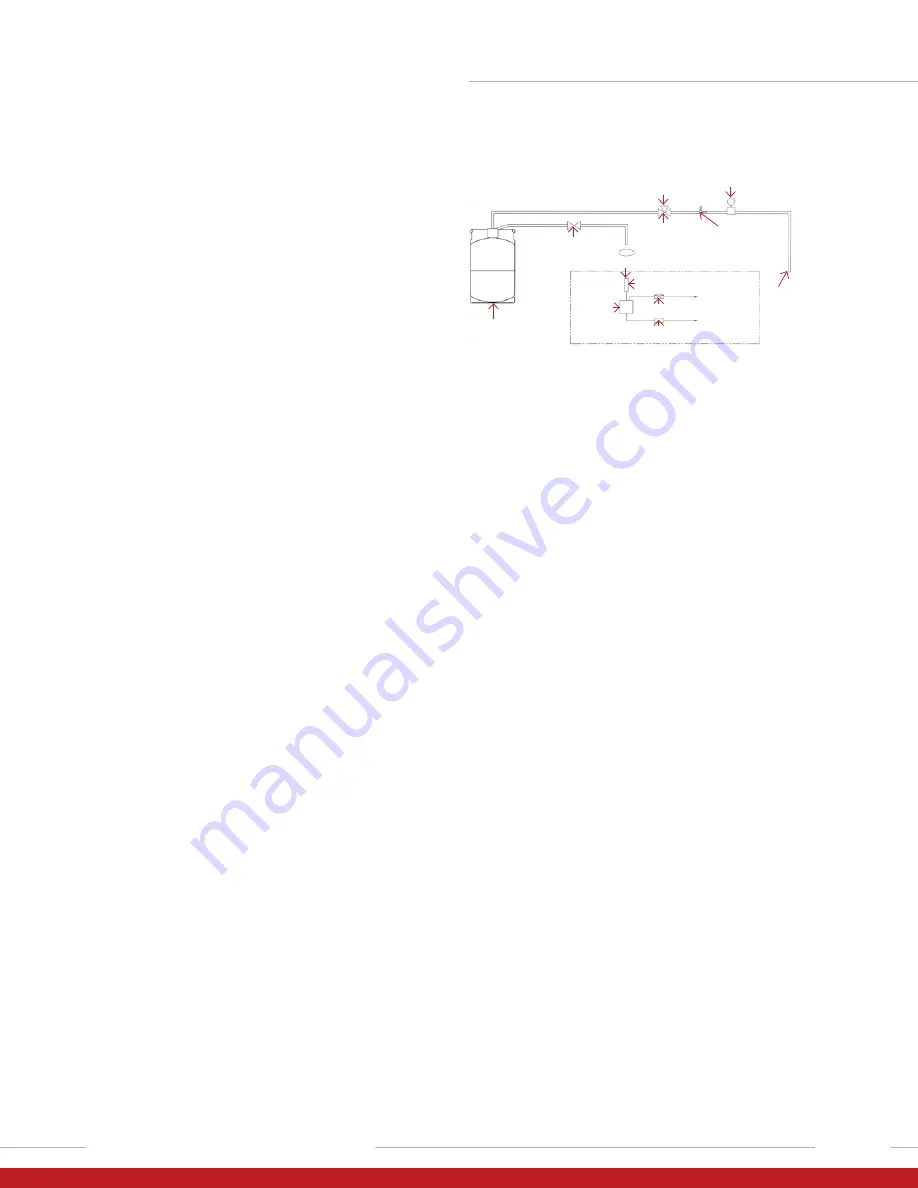
Figure 42 shows a typical example of how liner-based
canisters are connected to an end user’s production tool.
The actual connections and components vary, depending
on the user’s equipment and application, and on the type
of dispense connector used. However, all systems
provide inert gas pressure to the canister to dispense
chemical from the canister to the production tool.
NOWPak
canister
Chemical
source
container
Liquid dispense
control valve
Three-way
N2 pressure
control valve
Pressure
relief valve
Inert
gas
source
Vent
14.7 psig bar
maximum
regulator
To point of use
Drain valve
To chemical
drain
To point
of use
Chemical
in sensor
Chemical
out sensor
Reservoir
Optional
Figure 42. Typical pressure dispense chemical dispense installation.
END USER PROCEDURES
For the end user, normal canister system setup and
operation includes the following procedures.
• Install a dispense connector to the production tool.
• Connect the dispense connector to a filled canister.
• Dispense chemical from the canister.
• Change out empty canisters.
• Troubleshoot chemical leaks.
Installing a Dispense Connector to the Production Tool
Before connecting a canister, the end user installs one
of the three dispense connector types (ND-CD, ND-LD,
or MaxMT) to their production tool. This procedure
includes connecting the dispense connector to the
tool’s inert gas and chemical lines.
During dispense, the inert gas line pressurizes the
canister and chemical is dispensed through the
chemical line to the tool.
1. Connect one end of the inert gas supply line tubing
(typically a translucent, inert plastic such as PFA) to
a filtered and regulated gas source.
2. Connect the opposite end of the inert gas supply line
to the pressure inlet fitting on the dispense connector.
3. Connect the tool’s chemical line to the liquid
dispense fitting on the dispense connector.
NOTE: An optional depressurization kit can be installed
in the inert gas supply line to control the pressurization
and depressurization of the canister. See Changing Out
Empty Canisters, page 27, for important information on
depressurizing canisters before removing the dispense
connector from a canister.


