background image

 Wireless Video Door Phone 


FCC COMPLIANCE STATEMENT  

FCC ID: 

ERY-DP2661C7Q


THIS DEVICE COMPLIES WITH PART 15 OF THE FCC RULES. OPERATION IS SUBJECT TO THE FOLLOWING TWO CONDITIONS: (1) THIS DEVICE MAY 

NOT CAUSE HARMFUL INTERFERENCE AND (2) THIS DEVICE MUST ACCEPT ANY INTERFERENCE RECEIVED, INCLUDING INTERFERENCE THAT MAY 

CAUSE UNDESIRED OPERATION. 

Notice: The changes or modifications not expressly approved by the party responsible for compliance could void the user’s authority to operate the equipment. 

IMPORTANT NOTE: To comply with the FCC RF exposure compliance requirements, no change to the antenna or the device is permitted. Any change to the 

antenna or the device could result in the device exceeding the RF exposure requirements and void user’s authority to operate the device.


IMPORTANT:

 Users and installers of this product are responsible for ensuring this product complies with all national, state, and local laws and statutes related to 

monitoring and recording audio and video signals. SECO-LARM


will not be held responsible for the use of this product in violation of any current laws or statutes.


IMPORTANT:

 Users and installers of this product are responsible for ensuring that the installation and configuration of this product complies with all national, state, 

and local laws and codes. SECO-LARM will not be held responsible for the use of this product in violation of any current laws or codes.


California Proposition 65 Warning:

 These products may contain chemicals which are known to the State of California to cause cancer and birth defects or other 

reproductive harm. For more information, go to 

www.P65Warnings.ca.gov

.


WARRANTY:

 This SECO-LARM product is warranted against defects in material and workmanship while used in normal service for one (1) year from the date of 

sale to the original customer. SECO-LARM’s obligation is limited to the repair or replacement of any defective part if the unit is returned, transportation prepaid, to 

SECO-LARM. This Warranty is void if damage is caused by or attributed to acts of God, physical or electrical misuse or abuse, neglect, repair or alteration, improper 

or abnormal usage, or faulty installation, or if for any other reason SECO-LARM determines that such equipment is not operating properly as a result of causes other 

than defects in material and workmanship. The sole obligation of SECO-LARM and the purchaser’s exclusive remedy, shall be limited to the replacement or repair 

only, at SECO-LARM’s option. In no event shall SECO-LARM be liable for any special, collateral, incidental, or consequential personal or property damage of any 

kind to the purchaser or anyone else. 

NOTICE:

 The SECO-LARM policy is one of continual development and improvement. For that reason, SECO LARM reserves the right to change specifications 

without notice. SECO-LARM is also not responsible for misprints. All trademarks are the property of SECO-LARM U.S.A., Inc. or their respective owners. Copyright 

© 2022 SECO-LARM U.S.A., Inc. All rights reserved.
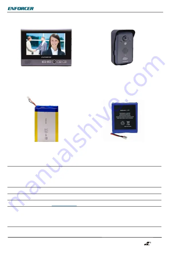


Accessories 

Additional Monitor 

Additional Camera 


DP-266-M7Q 

DP-266-CAQ 


Replacement Rechargeable Lithium-Ion 

Battery for Monitor 

Replacement Rechargeable Lithium-Ion 

Battery for Camera 


DP-266-BM7 

DP-266-BC 


SECO-LARM

 ® 

U.S.A., Inc.


16842 Millikan Avenue, Irvine, CA 92606 

Website: www.seco-larm.com 

Phone: (949) 261-2999  |  (800) 662-0800  Email: [email protected] 


PICKN1 


MI_DP-266-1C7Q_220607.docx 


Содержание DP-266-1C7Q

Страница 1: ... of sight range Actual range may vary depending on the installation and operating environment Additional monitors and camera sold separately Wireless operation camera and monitor can operate from up to 492ft 150m away Remotely and securely talk to visitors and unlock doors or gates via the monitor Monitor can be carried around the premises while talking to the visitor Connect up to two additional ...

Страница 2: ...ring Additional Monitors or Cameras on pg 14 Table of Contents Introduction 1 Parts List 2 Specifications 3 Overview 4 Display Overview 5 Installation Notes 5 Camera Wiring Diagram 6 Sample Application 6 Installation Camera 7 Installation Monitor 7 8 On Screen Display Features 8 Programming and Using the On Screen Display 9 10 Programming the Advanced Settings 10 11 Operating the Wireless Video Do...

Страница 3: ... lbs 544g Line of sight range Actual range may vary depending on the installation and operating environment Camera Type Color camera Chip CMOS Resolution 640 TV Lines Lens 2mm Field of view 170 Camera angle adjustment Up to 20 any direction Operating voltage 9 16 VAC 5 16 VDC Relock delay 3 6 8 Seconds Relay output 3A 24VAC 24VDC Current draw Active 300mA 12VDC Standby 15mA 12VDC Battery life Acti...

Страница 4: ...ons see pg 6 Reset button Battery cover Monitor Camera angle adjustment joystick Exit View Menu Unlock Right OK On Off Up Record Down Photo MicroSD Port Brightness Volume USB Power Cover Contrast Monitor Stand PIR Sensor IR LEDs Speaker Status LED Doorbell Microphone Camera Overview ...

Страница 5: ...splay Overview Installation Notes 1 Unpack the video door phone and note the included parts 2 Read this manual thoroughly A clear understanding of the manual will make installation and operation much easier 3 Find a location to mount the monitor and camera Approximately 5ft 1 5m above the ground is optimal where the visitor would stand approximately 2 5 5 ft 0 8 1 5 m from the camera NOTE The came...

Страница 6: ...amera Camera Wiring Diagram 1 Positive power input Connect to the red wire of the included AC adapter or to the positive wire of the doorbell s power supply 2 Negative power input Connect to the black wire of the included AC adapter or to the negative wire of the doorbell s power supply 3 Egress N O negative input Connect to an optional N O egress device The egress device will activate the relay f...

Страница 7: ...gh the wire hole in the bracket to the optional door unlock device 5 Install the rechargeable lithium ion battery into the camera The battery will act as a backup power source in case of a power outage 6 Connect the AC adapter see Camera Wiring Diagram pg 6 7 Install the monitor battery see below and turn on the camera and monitor If the camera is not in the bracket the tamper alarm will sound Pre...

Страница 8: ...and delete photos taken by the camera station There are four different types of photos M Photos taken by the user manually 1 photo taken A Photos taken by the camera station automatically when the doorbell button is pressed 1 photo taken T Photos taken by the camera station automatically when the unit is removed from the bracket and the tamper alarm activates 4 photos taken P Photos taken by the c...

Страница 9: ...e All to delete all photos after an additional prompt 5 Once viewing a photo press the Up or Down buttons to cycle through other photos 6 Press the OK button to either delete or exit the photo viewing mode and go back to the on screen display menu NOTES The monitor can save up to 240 photos Photos are saved in a first in first out method meaning that the system automatically deletes the oldest pho...

Страница 10: ...play 2 Highlight the Language icon and press the OK button to enter the Language screen 3 Use the Up and Down buttons to select a language English default German Spanish French Russian or Chinese 4 Press the OK button when finished programming to go back to the on screen display menu Programming the Advanced Settings 1 While the monitor display is on press the Menu Unlock button to open the on scr...

Страница 11: ...es 8 seconds Pairing See Resetting the Camera and Pairing a First Monitor and Programming Additional Monitors or Cameras on pgs 13 14 for information regarding the Pairing setting Alarm Setting 1 Select Alarm setting and press the OK button 2 Select On or Off to turn the tamper alarm on or off and press the OK button NOTE If multiple cameras are paired to the monitor then select the desired camera...

Страница 12: ... the monitor the camera station can still be heard on the indoor monitor 5 Press the Down Photo button on the monitor to take a manual photo 6 Press the Volume up down button to adjust the audio level 7 Press the OK button when finished with the call View and or Talk to a Visitor Who Has Not Pressed the Camera Doorbell Button 1 Press the OK or Power button to turn the monitor s display ON 2 Press ...

Страница 13: ...xt lowest ID monitor If monitor 1 is calling monitor 2 the user would press the Up button If monitor 3 is calling monitor 2 the user would press the Down button If monitor 3 is calling monitor 1 the user would press the Up button 5 Press the OK button when finished with the call Resetting the Camera and Pairing a First Monitor NOTE By default the monitor in the DP 266 1C7Q Complete Kit is paired w...

Страница 14: ...Code NOTES Up to three total monitors can be learned to the system The intercom feature will not function until the connection is confirmed by the new monitor To Pair an Additional Camera 1 Put the camera into pairing mode a Remove the camera from the bracket b If the tamper alarm is active then the alarm will begin to sound i Disconnect power from the camera by removing the battery and disconnect...

Страница 15: ...r Make sure the monitor s battery is charged Plug the charger directly into the monitor The monitor is not charging Remove the battery from the battery compartment and clean both the battery contacts and the monitor s connection contacts Make sure the kickstand is extended when placing in the charger stand Make sure the power adapter is correctly connected to the charger stand Connect the power ad...

Страница 16: ...arm For more information go to www P65Warnings ca gov WARRANTY This SECO LARM product is warranted against defects in material and workmanship while used in normal service for one 1 year from the date of sale to the original customer SECO LARM s obligation is limited to the repair or replacement of any defective part if the unit is returned transportation prepaid to SECO LARM This Warranty is void...

Отзывы: