ASSEMBLY AND USER MANUAL
Combi [6 | 12 | 16] & Combi 12 HT
14
www.energie.pt
5.2.8.
Fixation
The affixation of panels depends on the installation site and the method and type of affixation
is the installer’s
decision. However, you must bear various factors in mind (described above such as, for example, distance,
orientation…).
For a correct affixation of the panels, as regards the physical part of the affixation supports they must have a sturdy
structure in line with the circumstances of the site. Each panel must be secured at 6 points (as a minimum).
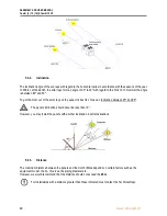
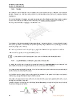
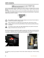
The image below illustrates an example of the affixation used:
The affixation of the panels is ensured by aluminium supports*. The support is bent in “L” form with two M8 through
holes. The support base is secured to the roof (where applicable) using an M6 screw and a plastic plug or a female
thread (depending on the situation).
The other support rib is secured to the panel by way of galvanised M6 screws to prevent corrosion situations.
*
The aluminium supports are not supplied with this product.
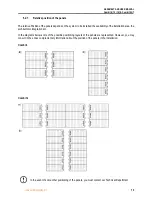
The Panels must have a minimum gap of 50cm (from the previous and/or subsequent panel)
5.2.9.
Liquid Distributor and Collector, placement and connection
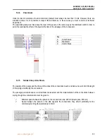
To ensure that the fluid reach the panels in homogeneous fashion, a
liquid distributor
must be installed. This
same distributor includes as many distribution tubes as there are panels in the installation.
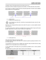
The distributor is placed between the panels. The connection tubes to the panels must have strictly the same length
and their ends connect directly to the panels.
The distributor and the collector may be placed before the installation of the panels for the sake of convenience
(obstruction, passage of distribution tubes behind the panels).
Only remove the pipe protection cover at the time of connection to the power and aspiration shafts with a view to
avoiding the penetration of impurities.
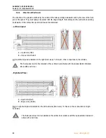
Install the distributor (s) vertically, face downwards (
never horizontally
!
), thereby ensuring that the fluid reaches
the panels in homogeneous fashion.
Содержание Combi 12
Страница 29: ...ASSEMBLY AND USER MANUAL Combi 6 12 16 Combi 12 HT www energie pt 29 8 2 Combi System 400 420 Vac 3 N 50 Hz...
Страница 31: ...ASSEMBLY AND USER MANUAL Combi 6 12 16 Combi 12 HT www energie pt 31 9 ANNEXES B INSTALLATION 9 1 Plan...
Страница 34: ...ASSEMBLY AND USER MANUAL Combi 6 12 16 Combi 12 HT 34 www energie pt...


