background image


Battery charger NG3 

English 


D01058-02


13


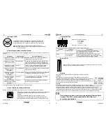
 LED 

Indicator 

RED LED shows that the battery is in the initial charging phase. 
YELLOW LED shows that the battery charger has reached 80% of charge. 
GREEN LED shows that the battery has reached 100% of charge. 

Further information can be found in the description of the Charging Curve. 

Example

: RED LED on with brief blinks indicates a constant tension phase. 


Alarms (Two-tone audible message) 

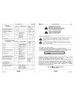
An two-tone audible message and the flashing LED shows that an Alarm situation has occurred: 

Condition Alarm 

Type 

Description 

(Action) 

Audible m 

RED flash 

Battery Presence  Battery disconnected or not in conformity. (Verify the 

connection and the nominal voltage). 

Audible m 

YELLOW flash 

Thermal Sensor 

The thermal sensor is disconnected during the re-
charge or it is out working range. (Verify the 
connection of the sensor and measure the 
temperature of the battery). 

Audible m 

GREEN flash 

Timeout 

Phase 1 and/or Phase 2 have a duration in excess of 
the maximal allowed. (Verify the battery capacity). 

Audible m 

RED-YELLOW flash 

Battery Current 

Loss of output Current control. (Failure of the control 
logic). 

Audible m 

RED-GREEN flash 

Battery Voltage 

Loss of output Voltage control. (Battery disconnected 
or failure of the control logic). 

Audible m 

YELLOW -GREEN flash 

Selection 

An unavailable configuration has been selected 
(Verify the selector’s position) 

Audible m 

RED-YELLOW-GREEN 

flash 

Thermal 

Overheating of semiconductors. (Verify the fan 
operation). 

When there is an alarm the battery charger stops supplying current. 


Thermal Sensor and/or External Indicator  

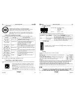
Thermal Sensor and/or External Indicator are Options that have to be connected to the 5 poles socket 
180°. 

Unless otherwise stated, the compensation of the Battery Voltage in 
function of the temperature of the Thermal Sensor is of -5mV/°C for 
battery cell. 
The control range of the Thermal Sensor goes from -20°C to +50°C. 

The External Indicator reflects exactly the LED Indicator which is placed 
on the equipment. 
Further information can be found in the description of the Charging Curve. 

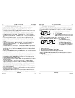
100%

START

80%

80%


 English 

Battery charger NG3 


14


 D01058-02


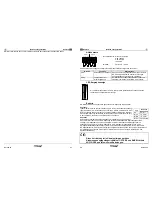
CURRENT

50%

100%

 Auxiliary 

Contacts 


Technical Features:  changeovers contacts 
 

 0,3A 125VAC 


 0,3A 110VDC 


 1A 30VDC 

Connector: 

 faston 6,3 

×

 0,8 mm 

Unless otherwise stated, the auxiliary contacts provide the following functions: 

Section Function 

Description 

AUX1 

Mains Presence 

When the equipment is switched on, the contact 
Normally Open (NO) CLOSES and instead the contact 
Normally Closed (NC) OPENS. 

AUX2 

End of charge or 
Trickle Phase 

When the Stop Phase or the No Stop Phase is reached, 
the contact Normally Open (NO) CLOSES and instead 
the contact Normally Closed (NC) OPENS. 

 LED 

Bar 

Graph 

The LED Bar Graph is an Option that shows a percentage indication of output current in 
comparison with its max. value 

Battery 

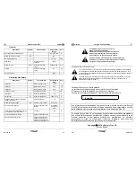
A battery is characterised by two sizes: tension and capacity. 

Tension: 

Each element has a nominal tension, which depends on the type of battery (no 
matter what size). 
In order to reach higher tension, many elements are connected in series, so 
creating a “BATTERY” of elements. 
The number of elements is calculated by dividing the nominal tension of the 
battery for the tension of each single element in the table: 

Capacity:


It is the quantity of electric charge that the batteries can supply to an external circuit before the tension 
decreases under the final limit value and it is obtained by multiplying the intensity of the discharging 
current 

I

, expressed in ampere (

A

), for the discharging time 

expressed in hours (

h

): 

C = I x t 

The traction battery capacity is normally referred to the discharging system of 5h: 

C5 = I x 5h. 

The capacity values  that can be recharged by the battery chargers can be found in the description of the 
Charging Curve (this value is not present in the curves able to charge any capacity). 


:


This device is in conformity with the Low Voltage directive 73/23/EEC 
and EMC directive 89/336/EEC and their further modifications.


NO

C

NC

NO

C

NC

AUX2

AUX1

Type 

Nominal 

Tension 

Pb 2 

V/cell 

NiCd 1,2 

V/cell 

NiMH 1,2 

V/cell 

NiZn 1,714 

V/cell 

Содержание NG3

Страница 1: ...ente grande per costituire un rischio di scosse elettriche per le persone Il punto esclamativo all interno di un triangolo equilatero avverte l utente della presenza di importanti istruzioni d uso e manutenzione servizio contenute nella documentazione allegata al prodotto Questa apparecchiatura è coperta da garanzia Il relativo certificato di garanzia si trova allegato al libretto di istruzioni Se...

Страница 2: ... di automobili a motore termico Evitare di ricaricare batterie non ricaricabili Verificare che la tensione nominale della batteria da ricaricare corrisponda a quella indicata nella targhetta del carica batteria Verificare che la curva di carica selezionata sia adatta al tipo di batteria che si deve ricaricare In caso di dubbio consultare il proprio rivenditore La Energic Plus HF declina ogni respo...

Страница 3: ...controllo della Sonda Termica va da 20 C a 50 C L Indicatore Esterno riproduce fedelmente l indicatore a LED posto sull apparecchiatura Ulteriori dettagli si trovano nella descrizione della Curva di Carica 100 START 80 80 Italiano Carica batteria NG3 6 D01058 02 CURRENT 50 100 Contatti Ausiliari Dati Tecnici contatti in scambio 0 3A 125VAC 0 3A 110VDC 1A 30VDC Connettore faston 6 3 0 8 mm Salvo di...

Страница 4: ...t Vin 230Veff 1 35 A Fattore di Potenza cosϕ P Pmax 0 68 Potenza Minima assorbita Pinmin Carica terminata 5 W Potenza Massima assorbita Pinmax P Pmax 3 kW Morsetti di Batteria Descrizione Simbolo Condizioni di Test Valore e o Range Unità Corrente di uscita I Vedi curva Corrente Massima di uscita I1 Fase 1 Vedi curva A Ondulazione della corrente di uscita I I1 5 Corrente assorbita Ia Apparecchiatur...

Страница 5: ...move cover Refer servicing to qualified service personnel Disconnect the mains supply before connecting or disconnecting the links to the battery Read the Instruction Manual carefully before use Verify that the selected charge curve is suitable for the type of battery You have to re charge Explanation of Graphical Symbols The lightning flash with arrowhead symbol within an equilateral triangle is ...

Страница 6: ... of non rechargeable batteries Verify that the nominal voltage of the battery to be re charged corresponds to the voltage stated on the battery charger name plate Verify that the selected charging curve is suitable for the type of battery to be re charged In case of doubt consult Your retailer Energic Plus HF will not accept any responsibility in case of mistaken choice of the charging curve that ...

Страница 7: ...icator reflects exactly the LED Indicator which is placed on the equipment Further information can be found in the description of the Charging Curve 100 START 80 80 English Battery charger NG3 14 D01058 02 CURRENT 50 100 Auxiliary Contacts Technical Features changeovers contacts 0 3A 125VAC 0 3A 110VDC 1A 30VDC Connector faston 6 3 0 8 mm Unless otherwise stated the auxiliary contacts provide the ...

Страница 8: ...ff Inrush Current Vin 230Veff 1 35 A Power Factor cosϕ P Pmax 0 68 Absorbed Minimum Power Pinmin End of charge 5 W Absorbed Maximum Power Pinmax P Pmax 3 kW Battery side Description Symbol Test Condition Value and or Range Unit Output current I See curve Maximum output current I1 Phase 1 See curve A Output current ripple I I1 5 Absorbed current Ia Equipment turned off 0 5 mA Output voltage U See c...

Страница 9: ...l utiliser lire attentivement le livre d instruction Vérifier que la courbe de charge sélectionnée est adaptée au type de la batterie qui doit être chargée Spécification des symboles graphiques Le symbole de flèche en forme d éclair à l intérieur d un triangle équilatéral averti l utilisateur de la présence de tension dangereuse non isolée à l intérieur du boîtier du produit cela peut être d ample...

Страница 10: ...roidi N employez pas pour charger des batteries installées à bord des voitures avec moteur thermiques Évitez la recharge des batteries non rechargeables Vérifier que la tension nominale de la batterie à recharger correspond à celle indiquer sur la plaquette du chargeur de batterie Vérifier que la courbe de charge sélectionnée soit adaptée au type de la batterie qui doit être rechargée En cas de do...

Страница 11: ...ie Signalisation acoustique VERTE clignotante Timeout La phase 1 ou 2 a une durée supérieure au maximum consenti vérifier la capacité de la batterie Signalisation acoustique ROUGE JAUNE clignotante Courant batterie Perte de contrôle du courant de sortie défaut sur la logique de contrôle Signalisation acoustique ROUGE VERTE clignotante Tension batterie Perte de contrôle de la tension de sortie batt...

Страница 12: ...nts Le nombre d éléments est calculé en divisant la tension nominale de la batterie pour la tension de chaque élément simple dans la table Capacité C est la quantité de charge électrique que les batteries peuvent fournir à un circuit externe avant que la tension diminue sous la valeur limite finale et elle est obtenue en multipliant l intensité du courant dérivé I exprimée en ampère A parce que le...

Страница 13: ...geur de batterie NG3 26 D01058 02 Généralités Description Symbole Conditions de test Gammes de valeurs Unité Gamme thermique de fonctionnement ΔT de 20 à 50 C Humidité relative maximum RH 90 Fréquence de commutation fc 30 5 kHz Rendement η Chaque condition de fonctionnement 85 Dimensions maximales a b c Sans les câbles de raccordement 430 220 90 mm Poids Sans les câbles de raccordement 5 5 kg Type...

Страница 14: ...as Gerät sollte auch den freien Zugang zu allen Anschluß Steckverbindern ermöglichen Schützen Sie den Lader vor eindringendem Wasser Das Eindringen jeglicher Flüssigkeiten in das Gehäuse muss vermieden werden Kontrollieren sie daß die verfügbare Netzspannung derjenigen entspricht die auf dem Geräte Typenschild vermerkt ist typisch in Deutschland 230Veff 50 Hz Im Falle von Unsicherheiten diesbezügl...

Страница 15: ...fgeladen ist Das grüne Lämpchen zeigt an dass die Batterie 100 der Aufladung erreicht hat Weitere Einzelheiten sind in der Beschreibung der Ladekurve zu finden Zum Beispiel Blinkend rote LED bei konstante Ladespannung Alarme akustik und Zweiton Eine akustische Zweiton und die aufblinkenden Lämpchen zeigen an dass ein Alarmzustand eingetreten ist Zustand Art des Alarms Beschreibung Aktion akustisch...

Страница 16: ...abhängt egal was Größe Um Hochspannung zu erreichen werden viele Elemente in der Reihe geschalten und so verursachen eine BATTERIE von Elementen Man teilt die nominale Spannung der Batterie für die Spannung jedes einzelnen Elements in der Tabelle um die Zahl von den Elementen zu errechnen Kapazität Es ist die Quantität der elektrischen Aufladung die Batterien an einen externen Stromkreis liefern k...

Страница 17: ...nrush Current Vin 230Veff 1 35 A Leistungsfaktor cosϕ P Pmax 0 68 Minimale Leistungsaufnahme Pinmin Ladeende 5 W Maximale Leistungsaufnahme Pinmax P Pmax 3 kW Batterie seitig Beschreibung Symbol Test Kondition Wert und oder Bereich Unit Ausgangsstrom nom I s Kurve Maximaler Ausgangsstrom I1 Phase 1 s Kurve A Stromripple I I1 5 Ruhestrom Ia Gerät abgeschaltet 0 5 mA Ausgangsspannung nom U s Kurve k...

Страница 18: ...ar o de desconectar los acoplamientos a la batería Leer con cuidado las instrucciones del manual Verificar que la curva seleccionada para el cargador sea correcta para el tipo de baterías que se tiene que cargar Explicación de los símbolos gráficos El símbolo flecha dentro de un triángulo equilátero alerta al usuario de la presencia de voltaje peligroso con los equipos encapsulados que puede ser d...

Страница 19: ...disponible corresponda al voltaje previsto e indicado en la tarjeta del cargador de baterías en caso de duda consultar al propio vendedor o a la sociedad eléctrica local Verificar que la curva requerida para el cargador es la correcta para la batería seleccionada En caso de dudas consultar al distribuidor Energic Plus HF no se hará responsable y no aceptará cargos por el mal uso o daños en cargado...

Страница 20: ...a 50 º C El indicador refleja exactamente el tipo de carga LED que se esta produciendo en el cargador Para más información puede ser encontrada en la descripción de curvas de carga 100 START 80 80 Español 40 D01058 02 CURRENT 50 100 Contactos auxiliares Características técnicas contactos de cambio 0 3A 125VAC 0 3A 110VDC 1A 30VDC Conector faston 6 3 0 8 mm Los contactos auxiliares están provistos ...

Страница 21: ...e entrada repentina Inrush current Vin 230Veff 1 35 A Factor de potencia cosϕ P Pmax 0 68 Mínima potencia absorbida Pinmin Fin de carga 5 W Máxima potencia absorbida Pinmax P Pmax 3 kW Aspectos de batería Descripción Simbolo Condición de test Valor o rango Unidad Corriente de salida I Ver curva Corriente máxima salida I1 Fase 1 Ver curva A Onda de salida corriente I I1 5 Corriente absorbida Ia Equ...

Страница 22: ...terij aan of los te koppelen Lees zorgvuldig de handleiding door voor gebruik Controleer of de gekozen laadcurve geschikt is voor het type batterij die u moet herladen Legende grafische symbolen De bliksemschicht in een gelijkzijdige driehoek dient om de gebruiker attent te maken op de aanwezigheid van niet geïsoleerde gevaarlijke voltages binnen de behuizing van de uitrusting welke voldoende hoog...

Страница 23: ... een elektricien teneinde het contactpunt te vervangen Gebruik geen adapter om de aarding te omzeilen Plaats niets op de kabel of leg deze niet waar erop gelopen kan worden teneinde schade eraan te vermijden Indien de kabel beschadigd of uitgerafeld is vervang deze dan onmiddellijk Indien u een verlengkabel of strip gebruikt verzeker u er dan van dat het totaal van de amperes vereist voor de total...

Страница 24: ...jke methode van werken voor de SMPS Switching Mode Power Supply bij hoog vermogen Deze oplossing levert een goede prestatie tegen een min kost en met min grootte gebruik makend van snellere en krachtigere schakelaars moderne technologie De grootste voordelen van deze oplossing zijn Hoge efficiëntie Kleinere afmetingen Korte oplaadtijden Opladen onafhankelijk van de veranderingen van de hoofdvoedin...

Страница 25: ...oor de batterijcel Het controlebereik van de thermische sensor gaat van 20 C tot 50 C De externe indicator geeft exact de LED indicator weer die geïnstalleerd is op de uitrusting 100 START 80 80 Nederlands 50 D01019 CURRENT 50 100 Verdere informatie kan gevonden worden bij de beschrijving van de laadcurve Hulpcontacten Technische Gegevens wisselcontacten 0 3A 125VAC 0 3A 110VDC 1A 30VDC Connector ...

Страница 26: ...n de EMC richtlijn 89 336 EEC en hun latere wijzigingen Nederlands 52 D01019 Mechanische afmetingen 90 220 370 430 78 6 N B Alle afmetingen zijn uitgedrukt in mm Gegevens voor het boren BOVEN Aanbevolen Installatie N B Alle afmetingen zijn uitgedrukt in mm 60 60 18 13 6 220 399 430 100 ...

Страница 27: ...el 0 2 mF Nederlands 54 D01019 Algemeen Omschrijving Symbool Teststatus Waarde en of bereik Een heid Werkingsbereik temperatuur ΔT van 20 tot 50 C Maximum relatieve vochtigheid RH 90 Switchfrequentie fc 30 5 kHz Efficiëntie η Bij elke status 85 Maximum grootte a b c zonder kabel 430 220 90 mm Gewicht zonder kabel 5 5 kg Bijlage klasse IP20 Bescherming en veiligheid Omschrijving Symbool Teststatus ...

Отзывы: