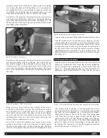
of the channels to keep the whole system level. See Figure
8.3. At the 4 corners, the short mitered pieces of liner hanger
rest on 4 triangular inside corner supports. Once the entire
system is laid out satisfactorily secure it down to the top
flange through the pre-drilled holes in the liner hanger. See
Figure 8.4. Over the channels, these fasteners should be
drilled through the channel and the flange. You may use a
pilot hole if you wish. Elsewhere, the fasteners must be drilled
through the washers and the panel flange.
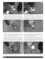
Caulk the gap between the liner hanger and the panel to ensure
that no water falling on the top flange of the pool panel can work
its way down behind the liner. See Figures 8.5 and 8.6. (With the
same objective in mind, later caulk the joint between the top of
the liner hanger and the coping that you install over the entire
top flange of the pool.)
9.Valve Assembly
If you have purchased the optional Aluminum Coping,
please refer to Section 14 and Technical Bulletin #4B prior
to proceeding with your assembly.
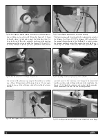
The Valve Assembly is included in a padded bag, found in
the System Control Board box, with the thru-wall fittings to
be installed on the front wall of the pool. See Figure 9.1.
Attach the Valve Assembly to the top flange of the front
panel as shown in the video. This valve controls the amount
of hydraulic fluid reaching the hydraulic motor, thereby
determining the speed of the water current. The Valve
Assembly is attached to the pool with self-drilling fasten-
ers, using the nut-driver bit provided. See Figure 9.2. Tech
Bulletin #3 explains all of the front panel connections
including these hydraulic connections in detail; the Tech
Bulletin is included in that padded bag.
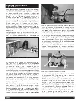
Remove the knob and shaft extension by loosening the
5/64" allen screw in the coupling. See Figure 9.3. Place the
Valve Assembly and rubber pad provided over the top
flange of the pool wall (aligning the hole in the Valve
Mounting Bracket with the small hole in the flange). See
Figure 9.4. Secure with 2 self-drilling screws. See Figure
9.5. Slip the shaft back through the holes and reattach.
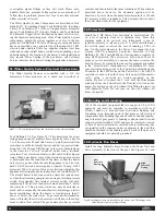
Fig 8.6: Caulking the liner hanger on the bottom.
Fig 9.3: Remove the knob and shaft extension.
Fig 9.2:Valve assembly attached to pool wall.
Fig 9.1: Front Panel Connections padded bag with Valve Assembly.
Fig 9.4: Align the hole in the valve bracket with the small hole in the panel.
10


