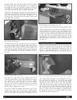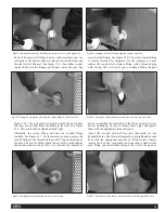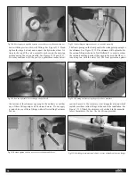
over-tighten plastic fittings as they will crack. Please note:
Endless Pools, Inc. provides Teflon sealant as a convenience. If
Teflon tape is preferred, please feel free to use that material.
Either material will work.
The Water Quality System Components are described in Tech
Bulletin #17 (Circulating Pump), Tech Bulletin #18 (Cartridge
Filter), Tech Bulletin #12 (Gas or Propane Heater discussed
above), Tech Bulletin #19 (Electric Heater), and Tech Bulletin
#20 (Nature2 Copper/Silver Purification System). After review-
ing the literature describing each of the Water Quality System
components, plumb the system together as shown in the dia-
grams in Tech Bulletin #16. Note: When a gas or propane heater
has been specified as an option in lieu of the standard 5.5 KW
electric heater, Endless Pools, Inc. supplies stainless steel heat
sinks and an indoor draft hood or outdoor top depending on our
understanding of the location of the heater. Some installations
may require Power Venting of the gas heater, call Customer
Service to discuss when Power Venting the gas heater is necessary.
35.Water Quality System Electrical Connections
The Water Quality System is controlled with a 110 volt
Intermatic Timer mounted on a board and described in
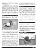
Tech Bulletin # 21. See Figure 35.1. This timer turns the circu-
lating pump on and off at preset times (typically twice a day for
3 to 4 hours each). Mount this timer on a wall protected from
rain above your Water Quality System and have your electrician
bring 110 volt, 20 amp GFCI power to the timer. Mounted next
to the timer is a 110 volt “switched” outlet with a twistlock
receptacle. Your electrician must wire this outlet to the adjacent
timer. When a gas heater is used, the electronic ignition system
is hard-wired into the load side of the timer so that the heater
only receives power when the circulating pump is on. The stan-
dard 5.5 KW electric heater requires a separate 30 amp, GFCI
protected, 220 volt service. Have your electrician hardwire this
appliance following the heater instructions in Tech Bulletin #19.
The electric heater is not connected to a timer but instead sens-
es when the circulating pump turns on using an internal pressure
switch. Occasionally, this internal pressure switch will need
readjusting if the level of the heater is much more than 5' below
the water level. This pressure switch can only be adjusted so
much and consequently the manufacturer discourages electric
heater installations where the heater is located more than 5'
above or below the water level. To get around this limitation,
some will install the electric heater on a shelf above the equip-
ment or add a flow switch. The gas heaters also have pressure
switches and theoretically the same limitations. When wired as
described above, however, the electronic ignition will be
deprived of power when the pump/timer/receptacle is off and
the pressure switch is redundant. Call Customer Service about
these elevation limits for the equipment.
36. Power Unit
Install the 5 HP Power Unit described in Tech Bulletin #22
on a level concrete floor in a sheltered area. Since this
machine needs to be serviced very infrequently it can be
installed remotely to reduce noise. It is often installed near
the electric panel to reduce the cost of running a 220 volt
line. On the wall adjacent to the Power Unit, mount the Len
Gordon AS5-TD pneumatic Controller described in Tech
Bulletin #23. The Controller/Power Unit requires a separate 30
amp, GFCI protected, 220 volt service. If you do not have 30
amps of service available, you can use the same circuit as the
Electric Heater by wiring both pieces of equipment as detailed
in the “Circuit Saver” instructions in Tech Bulletin #19. Have
your electrician bring power to the Controller and hardwire the
Controller to the 5 HP motor on the Power Unit. The AS5-TD
controller is used to turn the Power Unit on and off pneumati-
cally, using a poolside air button mounted in the
coping. Be sure to connect the 5' cord with the Hirschmann
connector from the Controller to the float-level switch on the
pump. Do not turn on the unit without first filling the reservoir
with hydraulic fluid. Do not turn on the unit without all
hoses connected.
37. Bonding and Grounding
All of the electrical equipment that we supply is UL or CSA
approved and must be installed in accordance with local
electric codes by a licensed local electrician. Bonding and
Grounding is an important part of that process. All electrical
components have bonding lugs and should be bonded together
and to the steel pool panels. A bonding conductor shall be solid
copper not smaller than 8 AWG and may be insulated, covered
or bare. If new construction is involved where reinforcing rods
are installed in the concrete under or adjacent to the pool this
should be included in the bonding circuit. Each of the pieces of
equipment should be separately grounded.
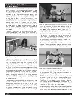
38. Hydraulic Run Hoses
Install the long hydraulic hoses between the Power Unit and
Valve Assembly at the front of the pool. See Figures 38.1 and
Fig 38.1: Hydraulic hoses are installed on the power unit.The fitting on the
filter/fill cap is the low pressure fitting.
Fig 35.1: 110 volt Intermatic Timer and “switched” outlet electrical board.
22
Low
Pressure
Fitting
High
Pressure
Fitting


