


ENDEVCO 6634C
INSTRUCTION MANUAL
IM6634C
Page 2-2
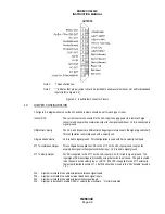
4.
SET JUMPERS
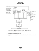
Before replacing cover, set the internal jumpers as desired. Jumper locations and settings are shown on Figure 2-4. W7
sets the DC Full Scale Output to 1V, 5V, or 10V, and W5 sets the AC Full Scale Output to 1V, 5V, or 10V (refer to Section
3.3 for more information). W1 selects Velocity Coil or RCC input in Model 6634C-XSF only (refer to Section 3.2 for more
information).
5.
POWER UP
Replace the cover and tighten the four screws in place. Then, plug the power cord into the power receptacle on the rear
of the unit and into an electrical receptacle with the appropriate voltage and frequency.
WARNING: TO PREVENT SERIOUS INJURY, ENSURE THAT THE COMMON CONNECTION OF THE POWER
OUTLET IS CONNECTED TO EARTH GROUND RETURN.
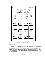
There is no power switch on unit. Unit is powered-up upon plugging power cord into live receptacle. On power-up, the
microprocessor runs a self-test. All LEDs are turned on for a few seconds during self-check. The serial interface address
will be displayed on the front-panel digital display for a few seconds, if the optional serial interface is installed. The front-
panel digital display will display an Error Message if a malfunction is detected. Front-panel error messages, which may
occur at power-up, are:
Err#
Description
Acknowledge by
Err2
EPROM Checksum Error
System Stop
Err3
RAM Error
System Stop
Err4
Setup RAM Checksum Error
<ENTER>
Err5
Calibration RAM Checksum Error
<ENTER>
Err6
Keyboard Error
System Stop
If an Error Message is displayed, go to Section 5 of this manual for trouble-shooting instructions. A steady numerical
display on the front-panel display indicator indicates that the Model 6634C is functioning correctly.
6. CHECKING OUT UNIT
How to check out the Model 6634C, using the front panel keyboard.
A.
INTERCONNECT SYSTEM
With the power turned OFF, connect an input cable and appropriate transducer to one of the inputs on the rear
panel of the Model 6634C. It is not necessary to connect output cabling at this time.
Turn on the power. The 6634C always powers up in "LOCAL" mode, in which the operating commands are taken
from the front panel keyboard. With the Serial Interface Board installed, the unit can be commanded to change to
the "REMOTE" mode by a Remote Command sent over the RS-232 bus (when the LOCAL/REMOTE pins are
connected together).