


ENDEVCO 6634C
INSTRUCTION MANUAL
IM6634C
Page 1-3
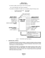
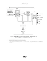
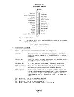
Figure 1-2 shows a simplified circuit of the Model 6634C. The optional Serial Interface, Six-Pole
Programmable Filter input (Model 6634C-XSF) are shown installed.
A.
INPUTS
The Model 6634C accepts inputs from:
•
External Calibration Source
•
Single-ended piezoelectric (PE) accelerometer
•
Differential PE accelerometer
•
Velocity Coil transducer (6634C), or jumper-selectable between Velocity Coil
transducer and Remote Charge Converter (6634C)
The Remote Charge Converter (RCC) input provides a constant current source to power Remote Charge
Converter electronics or Isotron accelerometers. The External Calibration input provides for inserting an
externally supplied signal for system gain verification and calibration.
B.
AMPLIFIERS AND FILTERS
The PE inputs (and the Ext Cal input) are amplified by a fixed-gain charge amplifier. The Velocity Coil input is
amplified by a fixed-gain instrumentation amplifier. The Remote Charge Converter input is amplified by the fixed-
gain voltage amplifier. Programmable switches configure these input stages to deliver the desired amplified signal
to the Sensitivity Amplifier. This stage is programmed to normalize the signal for the sensitivity of the sensor. This
normalized signal is delivered to the Broadband Output and can be filtered in the optional Six-Pole Filter or routed
directly to the next stages. The corner frequency of the optional Six-Pole Filter is programmable from the front
panel or over the RS-232 bus (with the optional Serial Interface). The External Filter can be used with or without
the programmable filter installed. (See Section 4.4.C)
C.
INTEGRATORS AND ANALOG OUTPUTS
The filtered or unfiltered output can be integrated once (to provide velocity data) or twice (to provide displacement
data). The filtered or unfiltered signals are delivered to the Accel-Out, Vel-Out, and Disp-Out Outputs. One of
these signals is switch-selected to be routed to the programmable gain Range Amplifier. The output of the
Range Amplifier is amplified in the fixed-gain AC Output Amplifier and delivered to the AC-Output. The Full-Scale
amplitude of the AC-Output can be set to 1V pk, 5V pk, or 10V pk using internal jumpers.
D.
DIGITAL OUTPUTS AND DISPLAY
The RMS value of the Range Amplifier output is converted to DC, which is then converted to 10-Bit digital data in
the A/D Converter. The microprocessor converts that data into engineering units and sends the value to the front
panel display. This same value is converted to an analog signal in the D/A Converter, amplified in the fixed gain
DC Output Amplifier, and delivered to the DC-Output. The Full-Scale amplitude of the DC-Output can be set to
1V, 5V, or 10V using internal jumpers.
E.
ALARMS
The digital amplitude data is compared to two pre-programmed alarm levels, and the microprocessor generates a
Warning Alarm and/or an Alert Alarm when the appropriate level is exceeded. In addition, the microprocessor
generates an Overload Alarm if the input to the A/D Converter (or any of the preceding amplifiers) exceeds the
saturation level for more than 3 seconds.