


ENDEVCO 6634C
INSTRUCTION MANUAL
IM6634C
Page 2-7
C.
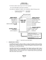
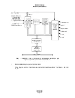
INTERCONNECT RS-232 INTERFACE
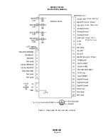
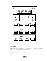
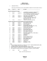
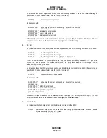
With the rack power off, plug in the cable connecting the computer/controller RS-232 interface to the RS-232
interface connector (optional) on the rear panel of the Model 6634C enclosure. The RS-232 Connector (Endevco
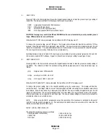
P/N EJ584) pin connections are shown in Figure 2-2.
Connect an input cable and transducer to the appropriate input connection on the rear panel of the Model 6634C
enclosure. It is not necessary to connect output cabling at this time.
The Model 6634C is ready to accept commands via the RS-232 interface. Send the appropriate RS-232
command strings to the Model 6634C using standard RS-232 conventions. Complete information on the use of
command strings is given in Section 4.
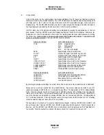
1
2
3
4
5
6
7
8
9
(J7)
PIN #
DESCRIPTION
1
ISOGND (Isolated from 6634C ground)
2
TRANSMIT
3
RECEIVE
4
Not Used
5
LOCAL/REMOTE
6
LOCAL/REMOTE
7
ISOGND (Isolated from 6634C ground)
8
Not Used
9
Not Used
Figure 2-2: Serial Interface (RS-232) Cable Connector Pinouts
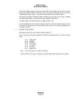
8.
ACCESSORY LIST
The following accessories are supplied with, or are optional for, the Model 6634C:
ITEM
PART NUMBER
QUANTITY
Power Cable
95-265V
17180
1
Connector
Twin BNC
EP316
2
Connector
25-pin, “D”
EJ600
1
Adapter
BNC F to 10-32
EJ21
Opt
Manual
IM6634C
1
Rack
4948
Opt
Programmable Filter
35840A
Opt
Serial Interface
35843
Opt