


ENDEVCO 6634C
INSTRUCTION MANUAL
IM6634C
Page A-1
APPENDIX A:
DETAILED THEORY OF OPERATION
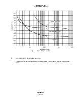
1.
AMPLIFICATION
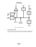
The ENDEVCO Model 6634C is a single-channel amplifier which provides a wide range of modes and gains.
The ENDEVCO Model 6634C Vibration Amplifier is a programmable amplifier system composed of an Input Amplification
Section, a Sensitivity Amplifier, a Filter Section (treated in Section A.3), and an Output Amplification (and integration)
Section.
A.
INPUT AMPLIFICATION
Input signals can be directed through a Charge Amplifier section or an Instrumentation Amplifier. (With the RCC
option, either the Instrumentation Amplifier or the RCC amplifier can be enabled by an internal jumper. The RCC
amplifier is discussed in Section A.2.)
The Charge Amplifier Section is used for single-ended or differential piezoelectric sensors, and can also be driven
by an AC voltage source (up to 10 V pk) into the Ext Cal input through an internal 1000 pF (±0.5%) coupling
capacitor. The maximum charge input must be limited to 33,000 pC pk and must be driven from a source
resistance of 10 Megohms, minimum. The 6634C can handle sensor sensitivities of 1.500 to 150.0 pC/g. The
Charge Amplifier operates at a fixed gain of 0.3030 mV/pC.
The Instrumentation Amplifier is used for velocity coil sensors and other voltage sources, and can be driven directly
by an external voltage source for calibration. The input connection is differential and provides 100 kilohms input
impedance. The 6634C can handle sensor sensitivities of 15.00 to 1500.0 mV/ips. The Instrumentation Amplifier
operates at a fixed gain of 0.0606 mV/mV.
B.
SENSITIVITY AMPLIFIER
The Sensitivity Amplifier input is programmable switched between the Charge Amplifier output and the
Instrumentation Amplifier output. The Sensitivity Amplifier gain can be programmable adjusted from 1.1 to 110 in
steps of 0.1%. The output of the sensitivity amplifier is available at the BB-OUT connector pin. It is also routed to
the optional programmable filter or directly to the following integrator stages.
C.
INTEGRATORS
The output of the Sensitivity Amplifier (or optional Filter) is routed to the Integrator stages and is available at the
ACCEL-OUT connector pin. The first (Velocity) integrator provides a 6 dB/octave transfer function rolloff, with
unity gain at 122.8 Hz. The output of the velocity integrator is available at the VEL-OUT connector pin, and is
routed to the input of the second (Displacement) integrator. The displacement integrator provides a 6 dB/octave
transfer function rolloff, with unity gain at 636.6 Hz. The output of the displacement integrator is available at the
DISP-OUT connector pin.
The ACCEL-OUT, VEL-OUT, and DISP-OUT signals are normalized to fixed sensitivities; the Acceleration Output
is 50 mV/g pk, the Velocity Output is 100 mV/ips pk, and the Displacement Output is 200 mV/mil pk-pk.
D.
RANGE AMPLIFIER
The Range Amplifier input is programmable switched between the signals at the ACCEL-OUT, VEL-OUT, or
DISP-OUT connector pins. The Range Amplifier gain can be programmable adjusted from 1 to 100 in steps of
0.1%. The output of the Range Amplifier is buffered in a gain of 0.1 and provided at the AC-OUT connector pin.
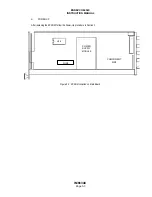
The output amplifier gain can be selected to 0.5 or 1.0 by using the W5 internal jumper. See Figure 2-4 for
jumper locations.