EMSD5 AC Servo Manual
Chapter 4 Wiring and Introduction
31
Terminal
CN3
Name
CN4
Name
Picture
1
NC
Null
NC
Null
2
E0V
CAN ground
E0V
CAN ground
3
CAN H
CAN Bus
communication
CAN H
CAN Bus
communication
4
RS485 -
RS485
communication
RS485 -
RS485
communication
5
RS485+
RS485+
6
CAN L
CAN Bus
CAN L
CAN Bus
7
GND
485 ground
GND
485 ground
8
NC
Null
NC
Null
4.6.3 RS485 Communication Connection Introduction
1.Connection With RS485 of A PLC
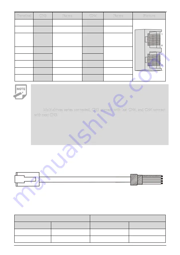
A connection cable between the driver and the PLC is as follows:
A
B
Fig.4-13 The Communication Cable Of Servo Drive With PLC
Table 4-2 Connection Between Servo Drive And PLC Communication Cable
Drive RJ45( A end)
PLC
(
B end
)
Signal Name
Pin No.
Signal Name
Pin No.
RS485+
5
RS485+
5
RS485-
4
RS485-
4
◆
It can connect PC or the upper controllers through a special serial port cable,
and it is forbidden to plug with electric.
◆
It is recommended to use twisted pair or shielded wire, the length of the wire
is less than 2 meters.
◆
Multi-drives series connected, CN3 connect with last CN4, and CN4 connect
with next CN3.
◆
When using RS485 bus communication and RS485 ground signal of the
upper controller is connected to the earth (PE), please connect PE terminal of the
upper controller with the drive terminal properly. In this case, it is forbidden to
connect RS485 ground signal of the upper controller with the drive RS485 ground
signal (GND), otherwise the driver may be damaged.


