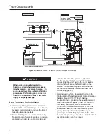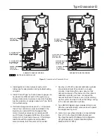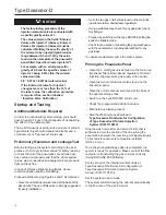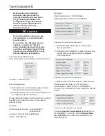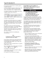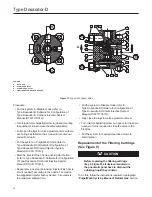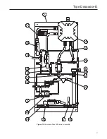
Figure 11.
Type SA/2 Supply Filter
21
V
2
3
4
5
6
7
8
9
10
11
12
13
14
15
16
17
18
19
20
1
A
A
H
R
M
Sez.A-A
H
H
M
R
V
- Entrata/Uscita acqua
- A monte delregolatore
Up
- Al raccordo di alimentazione
del pilota
- A valle del regolatore
Water Inlet/Outlet
stream of the regulator
To the feeding of the pilot
Downstream of the regulator
LEGEND
H - NOT USED
M - STABILIzER INLET
R - STABILIzER OUTLET
V - PIPELINE REFERENCE PRESSURE
21
V
2
3
4
5
6
7
8
9
10
11
12
13
14
15
16
17
18
19
20
1
A
A
H
R
M
Sez.A-A
H
H
M
R
V
- Entrata/Uscita acqua
- A monte delregolatore
Up
- Al raccordo di alimentazione
del pilota
- A valle del regolatore
Water Inlet/Outlet
stream of the regulator
To the feeding of the pilot
Downstream of the regulator
Procedure:
• Put the system in Disable mode (refer to
Type Dosaodor-D Software for Configuration of
Type Dosaodor-D Odorant Injection System
Manual (D103117X012));
• Turn injector valve adjusting screw in (closed) counting
the number of turns to close the valve completely;
• Fully open the injector valve adjustment screw (there
are O-rings installed so the screw will not come out
and will not leak);
• Put the system in Purge/Wash mode (refer to
Type Dosaodor-D Software for Configuration of
Type Dosaodor-D Odorant Injection System
Manual (D103117X012));
• Start the injector Flush Cycle pushing start button
(refer to Type Dosaodor-D Software for Configuration
of Type Dosaodor-D Odorant Injection System
Manual (D103117X012));
• Repeat previous step (increasing “injector Flush Cycle
time if needed”) according to the needs. 1 second is
the suggested injector flush cycle time, 5 seconds is
the maximum allowed time;
• Put the system in Disable mode (refer to
Type Dosaodor-D Software for Configuration of
Type Dosaodor-D Odorant Injection System
Manual (D103117X012));
• Fully close the injector valve adjustment screw;
• Turn injector adjusting screw out (open) for the same
number of turns required to close the valve in the
first step.
• Put the system in required Operation mode to
start injection.
Replacement of the Filtering Cartridge
(See Figure 9)
CAUTION
Before replacing the filtering cartridge
(key 6, Figure 9), all devices mounted on
the pneumatic panel have to drain out the
odorizing liquid they contain.
To do this, follow the instructions reported in paragraph
“
Purge/Wash Cycle by Means of Natural Gas
” section.
20
Type Dosaodor-D

