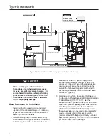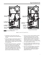
Most frequent combinations.
A. 1 and 6 with 4 and/or 5
B. 2 and 3 with 6
C. 4 and/or 5 with 6
D. 2 and 3 should be used together
Pneumatic Panel Installation
Pneumatic Panel should be installed in the immediate
vicinity of the odorant pick-up point (absorption-type tank
or other type of tank).
All of the panel components are resistant to chemical
attack from all of the odorizing liquids, to the elements
and to those conditions specified in regulations
regarding safety and electrical equipment.
It is essential that the distance between the panel and
the injection location be as short as possible, as a
short route limits the quantity of odorant subjected to
pressure and thus reduces the chances of leakage of
liquid occurring.
The pneumatic panel (Figure 3) is intended to be
wall mounted. Two spacing brackets are part of the
standard equipment supplied with the panel. The
standard equipment contains two brackets, standard or
extended injection wick, odorant filter and screws.
Four openings are provided for pipe connections and
they are located at the end points of the support panel.
The positions and sizes of the openings can be easily
identified from Figure 6.
Pneumatic Lines and Connections
The pneumatic connections between the
Type Dosaodor-D panel, the gas line and the odorant
tank should be carried out using stainless steel piping
only. Refer to Figure 6 for pipe sizes.
CAUTION
The pipeline connecting the
Type Dosaodor-D panel with the
odorant tank should be configured to
avoid the creation of possible air/gas
pockets (obstacles to the odorant flow).
Piping should be installed as straight as possible, with
a constant grade and without any sequences of upward
and downward inclines.
Polytetrafluoroethylene (PTFE) tape or thread sealer
should be used on all pipe fittings to prevent
odorant leakage.
Type ROC809 Controller Installation
Planning is essential to a good installation. Because
installation requirements depend on many factors,
such as the application, location, ground conditions,
climate and accessibility, this document only provides
generalized guidelines.
!
WARNING
Failure to follow the following installation
requirements could result in equipment
malfunction and loss of odorant
injection. Loss of odorant in the natural
gas supply could result in personal
injury and property damage from
undetected leaking natural gas.
Level Float and Switch Wiring
Type ROC809 must not receive the signals directly
from the odorant calibration cylinder (low and high
level). For safety reasons a barrier must be installed.
Barriecifications
Verify connection cable and field device capacitance
and inductance do not exceed the limits given for the
Intrinsically Safe barrier.
Level Switch Safe Parameters:
Ci (Equivalent input capacitance) = 20pF
Li (Equivalent input inductance) = 4μH
If the results are negative, condition 3 prevails on 2, since
cable resistance reduces circuit current (consequently
reducing the stored electrokinetic energy).
Cable parameters:
Cc (Equivalent input capacitance)
Lc (Equivalent input inductance)
Rc (Equivalent input resistance)
Environmental Requirements
NOTICE
The ROC809 requires protection
from direct exposure to rain, snow,
ice, blowing dust or debris and
corrosive atmospheres.
10
Type Dosaodor-D


