78 Chapter 5 Use Of Monitoring Module M800D
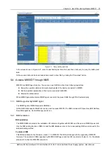
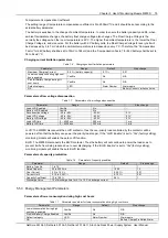
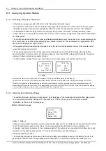
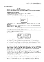
1. Test End Voltage, Test End Time, and Test End Capacity:
The M800D has battery test function and can record 10 groups of battery test data. The test data can only be queried
through MC. First, the user starts the battery test manually, the M800D regulates the rectifier output voltage according
to the setting of “Test End Voltage” to make the rectifier output voltage be lower than the battery voltage, and then the
battery starts to discharge. If the battery voltage reaches the setting of “Test End Voltage” or the battery discharging
time reaches the setting of “Test End Time” or the battery capacity reaches the setting of “Test End Cap”, the M800D
will stop the battery test and regulate the rectifier output voltage to normal Float Charge Voltage. The rectifier then
starts to charge the battery and the DC Power System transits to battery auto management mode. Meanwhile, the
M800D will record the battery test start/end time, battery test voltage and battery remaining capacity in the battery
test log. The user can query the test log from the M800D through MC.
During battery test, if the DC Power System has a fault, the M800D will stop the battery test automatically.
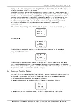
2. Planned Test Enabled
“Planned Test” means the M800D starts the battery test in a specific schedule.
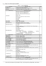
Table 1.2 Alarm for battery test
Default category
LED
Alarm number
Alarm name
OA
Y
081
Battery test in progress
OA
Y
082
Short Test in progress
OA
Y
083
Test End for Voltage
OA
Y
072
Discharge Current Imbalance
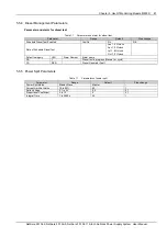
Boost charging parameters
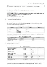
Table 1.3 Boost charging parameters
Parameter
Range
Default
Step change
Automatic Boost Charge Enabled
Yes/No
No
-
Cyclic Boost Charge Enabled
Yes/No
No
-
Nominal Voltage
48V: -53 ~ 59.5V
-53.5V
0.1V
Boost Voltage
48V: -53 ~ 59.5V
-56.4V
0.1V
Maximum Boost Charge Time
1 to 100 h
12 h
1 h
FC to BC Current
0.05 to 0.08 C
10
0.06 C
10
0.001 C
10
FC to BC Capacity
1 to 100%
80%
1
BC to FC Current
0.005 to 0.05 C
10
0.01 C
10
0.001 C
10
BC to FC Delay
0 to 600 min
180 min
10 min
Cyclic Charge Interval
2 to 365 days
180 days
1 day
Cyclic Charge Duration
180 to 720 min
300 min
1 min
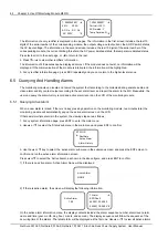
1. Automatic Boost Charge Enabled
When “Auto BC Enable” is enabled, DC Power System will start boost charge to the battery when the system meets
the boost charge conditions.
2. FC to BC Capacity and FC to BC Current
When battery capacity downs to the setting of “TO BC Capacity” or the battery current reaches the setting of “To BC
Current”, M800D will control the DC Power System to make it start boost charging to the battery. The battery charging
voltage is the setting of “BC Volt”(Boost Charge Voltage).
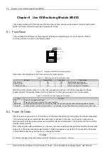
Table 1.4 Alarms for boost charging
Default category
LED
Alarm number
Alarm name
OA
Y
Cyclic Boost Charge
OA
Y
Automatic Boost Charge
OA
Y
Manually Boost Charge
OA
Y
Abnormal Battery Current
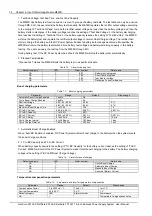
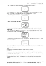
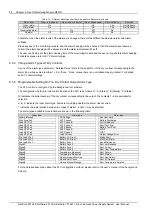
Temperature compensation parameters
Table 1.5 Parameter and alarm for temperature compensation
Parameter
Range
Default
Step change
Compensation Factor
0 to 2500mV/
C
72mV/
C
1mV/
C
Nominal Temperature
20 to 25
C
25
C
1
C
Default category
LED
Alarm Number
Alarm name
OA
Y
Temperature Compensation Active
NetSure 501 A50, NetSure 501 AA0, NetSure 701 A51 19-Inch Subrack Power Supply System User Manual


