Chapter 4 Use Of Monitoring Module M500D 15
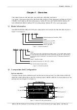
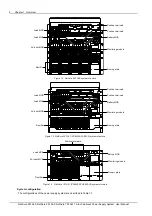
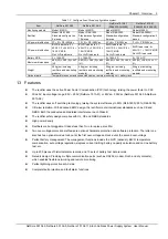
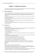
3) Settings
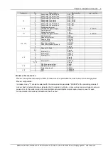
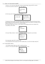
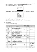
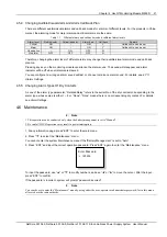
Including the setting of alarm parameter, battery parameter, AC/DC parameter, rectifier parameter and system
parameter.
4.3 Querying System Status
4.3.1 First Page Of System Information
1. At the main menu page, press “ESC” to return to the first system information page.
2. If no operation is conducted on the monitoring module keypad for 8 minutes, the LCD will return to the first system
information page and shut down the back light to protect the screen. Pressing any key will turn on the back light.
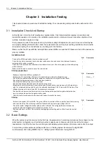
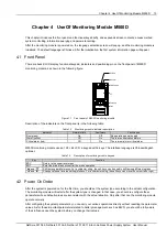
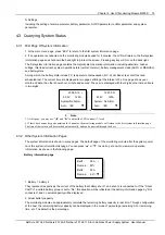
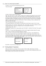
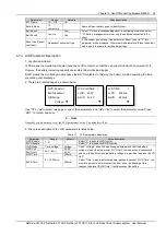
The first system information page contains the major system operation information, including date/time, busbar
voltage, total load current, system operation state (normal or alarm), battery management mode (AUTO or MANUAL)
and battery state.
Among which, the battery state include FC, temperature compensation, BC, Cyclic Boost, test, short test and
scheduled test. The current time are displayed in two pages shifting at the interval of 2s. One page shows year,
month and date, the other shows hour, minute and second. The year is displayed with four digits; other time units are
in two digits.
2004-5-12
53.5V 125A
System:No Alarm
Auto /BC
▼
自动均充
Or
12:20:30
53.5V 125A
System:
No Alarm
Auto /BC
▼
自动均充
3.
Note
1. At this page, you may use “
◄
” and “
►
" to adjust the LCD contrast (7-level).
2. If there has been no keypad operation for 8 minutes, the monitoring module will return to the first system information page.
The time of that return will be recorded automatically, and can be queried through the host.
4.3.2 Other System Information Pages
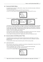
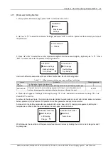
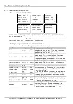
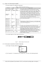
The system information is shown in many pages. The default page of the monitoring module after the system power
on is the system information first page. You can press “▲” or “▼” to scroll up or down to view more operation
information, as shown in the following page:
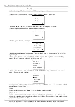
Battery information page
Batt1: 50A
Remain : 60
%
Batt2: 50A
Remain: 60
%
▼
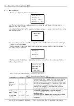
1. Battery 1, battery 2
They represent respectively the current of the battery that battery shunt 1 and shunt 2 is connected to. If the “Shunt
Coeff” of a certain battery group is set to “No”, this situation will be reflected at the battery information page by “Not
connected”, and no actual capacity will be displayed.
2. Actual battery capacity
The monitoring module can approximately calculate the remaining battery capacity in real time. Through configuration
at the host, the remaining battery capacity can be displayed in the mode of percentage, remaining Ah or remaining
time, etc. The default is the percentage.
NetSure 501 A50, NetSure 501 AA0, NetSure 701 A51 19-Inch Subrack Power Supply System User Manual

