Chapter 5 Use Of Monitoring Module M800D 61
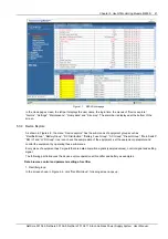
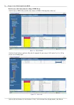
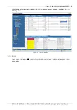
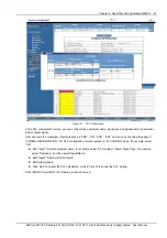
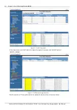
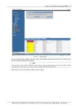
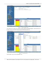
Figure 2.1 PLC Configuration
In the PLC configuration screen, you can configure the equipment name, signal type and signal name to generate a
kind of output signal.
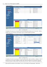
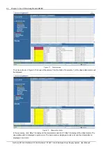
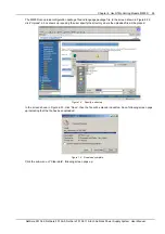
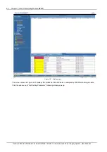
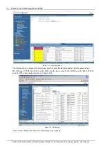
User can learn the meanings of symbols such as “AND”, “OR”, “XOR”, “NOT” and so on by checking the page of
“SYMBOLS INFORMATION”. For PLC configuration, Select operator in “PLC CONFIG” page, for example, select
“OR”;
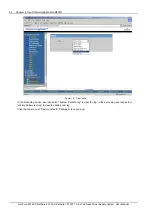
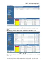
Edit “Input1”: Select equipment name, for example, select “ACU System”; Select Signal Type, for example,
select “Sampling”, and then select SignalName;
Edit “Input2”: Same with “Edit Input1”;
Edit output signals;
Click “Add” to enable the PLC calculation, or click “Cancel” to cancel the PLC setting.
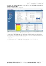
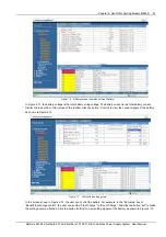
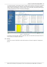
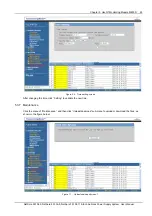
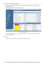
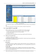
Click “Edit GC PowerSplit”, the following screen shows up:
NetSure 501 A50, NetSure 501 AA0, NetSure 701 A51 19-Inch Subrack Power Supply System User Manual

