16 • MultiFlex I/O Board Operator’s Guide
1. Connect the input to the point labeled
INPUT #1. This is the only point on the
board that may accept this type of input.
2. Locate switch #8 on the dip switch bank
labeled S3 (the same one that sets input
board network ID). Set switch #8 to the UP
(ON) position. This will tell the REFLECS
that the input on point #1 is a pulse accumu-
lation input.
4.1.2. Power Connection
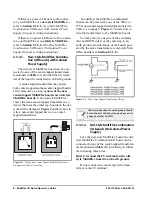
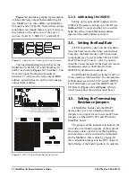
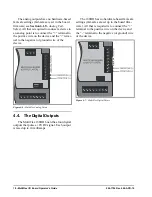
If power is needed to operate the sensor, four
points are provided on the MultiFlex board that
supply DC power: one +12VDC point, and three
+5VDC points. See
for the location
of these points.
4.1.2.1.
Current Ratings for On-Board
Power Sources
The maximum current that may be drawn
from the +12VDC terminal is 100 milliamps.
The maximum current that can be drawn from
all three +5VDC terminals COMBINED is 50
milliamps.
4.1.2.2.
Powering Sensors Requiring
24VAC Off the Power Transform-
er
Some sensors that requires 24VAC can be
powered off the MultiFlex’s own 24VAC power
connection. To connect to the 24VAC power
source, connect the sensor’s power wires to ter-
minals AC1 and AC2.
This can only be done with sensors that keep
the 24VAC signal isolated from its DC output
signal (such as CPC’s Dew Point Probe). If the
output signal is not isolated from the 24VAC
input, you must use a separate transformer.
4.1.3. Sensor Types for MultiFlex In-
put Points
Because different controllers may be com-
patible with different sensor types, this manual
cannot list all sensor types and how to wire them
to a MultiFlex input point. Refer to your site
controller’s documentation for sensor wiring
information.
4.2. The Relay Outputs
The MultiFlex Combination I/O boards have
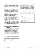
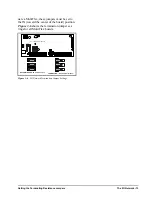
shows how to
wire the three-terminal Form C contact.
One wire of the two-wire connection should
always be connected to the middle terminal. The
second wire must either be connected to the N.C.
terminal (if you want the path to be closed when
the relay is de-energized) or the N.O. terminal (if
you want the path to be open during power fail-
ure).
The contacts you choose also affect what the
board’s fail-safe dip switch will need to be set to
for proper operation. Refer to
4.2.1. Output Fail-Safe Dip Switches
When a controller calls for a MultiFlex relay
output to be ON, it sends a command to the Mul-
tiFlex to turn the output to the ON state (signi-
fied by the output LED being ON). The behavior
of the relay when it is ON is determined by the
Figure 4-4 - Input Board Power Sources
+5 VDC
+12 VDC
Figure 4-5 - Form C Contact Wiring
N.C. N.O.
N.C. N.O.
RELAY IS
CLOSED
ON POWER
FAILURE
RELAY IS
OPEN ON
POWER
FAILURE
Содержание 810-3013
Страница 1: ...026 1704 Rev 6 06 APR 10 MultiFlex I O Board Installation and Operation Manual ...
Страница 2: ......
Страница 4: ......
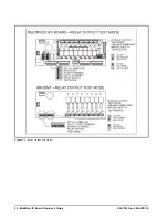
Страница 36: ...30 MultiFlex I O Board Operator s Guide 026 1704 Rev 6 06 APR 10 Figure 7 1 Relay Output Test Modes ...

