24 • MultiFlex I/O Board Operator’s Guide
6.1.6. Input Screens
6.1.6.1.
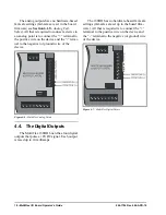
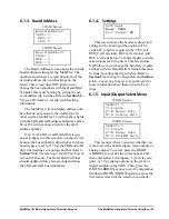
Input Status/Config Menu
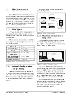
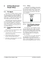
The Input Status/Config Menu offers three
choices:
1.
STATUS-VOLTS -
Selecting this option will
show the status of all the inputs in volts.
2.
STATUS-ENG UN -
Selecting this option
will show the status of all the inputs in engi-
neering units. Engineering units must be
specified for each input using the Input Con-
fig screens (option 3), or else the board as-
sumes the input is a temperature sensor and
will display the input value in degrees Fahr-
enheit.
3.
INPUT CONFIG -
Selecting this option will
allow you to specify the engineering units for
each sensor connected to an input. Doing this
will allow you to see the sensor value in terms
of its intended engineering units.
6.1.6.2.
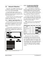
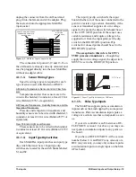
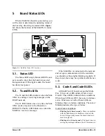
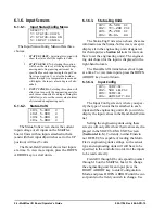
Status-Volts
The Status-Volts screen shows the current
input voltage of all inputs on the MultiFlex
board. Units with no inputs attached to them
(and with their input dip switches set to the UP
position) will read 5 volts.
The Hand-Held Terminal shows four inputs
at a time. To view more inputs, press the DOWN
ARROW key to scroll down.
6.1.6.3.
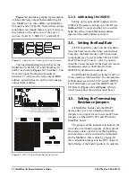
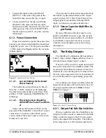
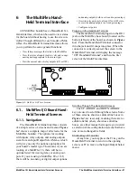
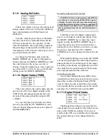
Status-Eng Units
The Status-Eng Units screen shows the same
information as the Status-Volts screen, except it
displays it in the engineering units designated
for that input (see
for more on
how to set the engineering units). The engineer-
ing unit chosen for the input is displayed in the
right-hand column.
The Hand-Held Terminal shows four inputs
at a time. To view more inputs, press the DOWN
ARROW key to scroll down.
6.1.6.4.
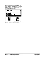
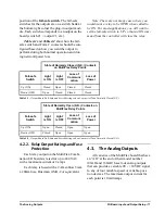
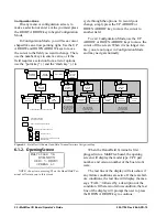
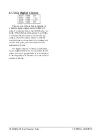
Input Config
The Input Config screen is where you spec-
ify the type of sensor that is attached to each
input and the engineering unit with you wish to
display the input values in the Hand-Held Termi-
nal.
Setting the engineering units using these
screens will only affect how their values are dis-
played in the STATUS-ENG UNITS screen
(
). Currently, neither Einstein
nor REFLECS is capable of reading the Multi-
Flex’s engineering units settings, so the sensor
type and engineering units will still have to be
specified in the controller in order for the inputs
to be read correctly.
Fields I01 through I16 correspond to points 1
through 16 on the MultiFlex board. To change
the engineering unit for an input, press the
RIGHT ARROW key to enter Configuration
Mode, and press DOWN ARROW until the cur-
sor points to the field you wish to change. Use
SELECT: 1
1= STATUS-VOLTS
2= STATUS-ENG UN
3= INPUT CONFIG
I01: 5.000 V
I02: 5.000 V
I03: 5.000 V
I04: 5.000 V
I01: 74.500 DF
I02: 111.200 PSI
I03: 75.200 DF
I04: 65.04 RH
I01: TEMP-DF
I02: 500 LB-PSI
I03: TEMP-DF
I04: HUMIDITY-RH
Содержание 810-3013
Страница 1: ...026 1704 Rev 6 06 APR 10 MultiFlex I O Board Installation and Operation Manual ...
Страница 2: ......
Страница 4: ......
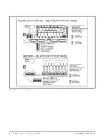
Страница 36: ...30 MultiFlex I O Board Operator s Guide 026 1704 Rev 6 06 APR 10 Figure 7 1 Relay Output Test Modes ...

