


10 • MultiFlex I/O Board Operator’s Guide
3
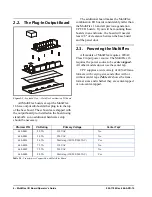
The I/O Network
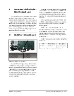
All MultiFlex boards and controllers use an
RS485 network connection to communicate with
Einstein and REFLECS site controllers. Techni-
cians who are familiar with CPC’s previous gen-
eration 16AI, 8IO, and ARTC boards will find
the network setup procedure for the MultiFlex
boards to be very much the same.
3.1. Wire Types
CPC specs Belden #8641 shielded twisted
pair cables for use as I/O network wiring (or
Belden #82641 and Belden #88641 for plenum
installations).
If the recommended cable is not available in
your area, be sure the wiring meets or exceeds
the following specs:
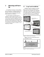
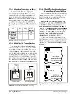
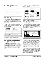
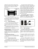
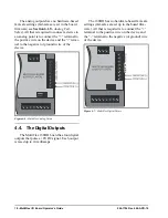
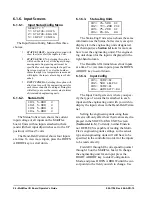
3.2. Network Configuration
(Daisy Chains)
The RS485 Input/Output (I/O) network is
wired in a daisy-chain configuration. In a daisy
chain, boards are wired together in series with no
branches or "star configurations," and the net-
work is terminated at either end of the daisy-
chain.
A diagram of this network arrangement is
shown in
.
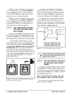
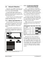
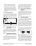
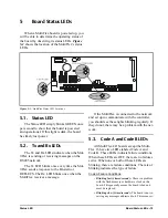
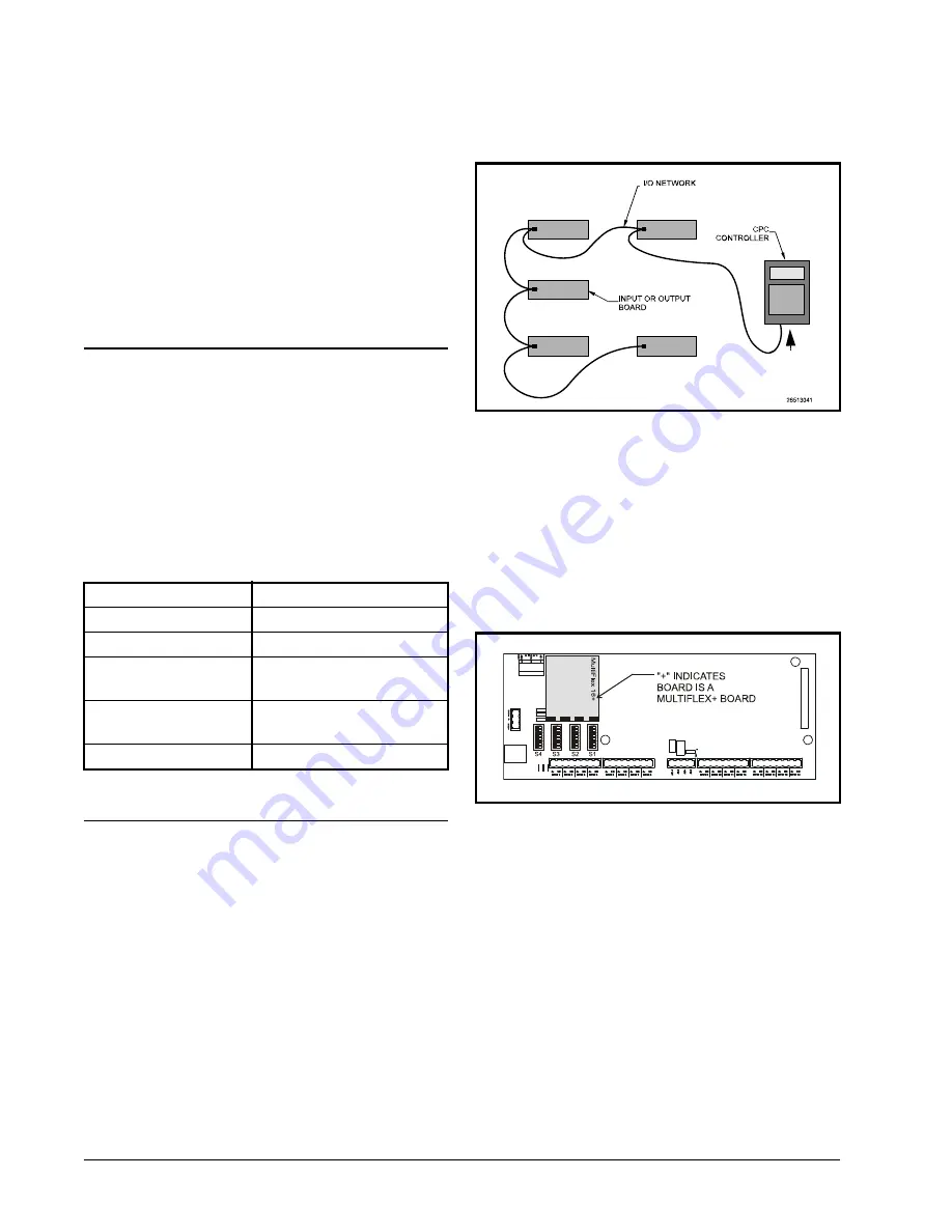
3.2.1. Maximum # of Boards on a
Daisy Chain
To determine how many MultiFlex control-
lers may be daisy-chained together, look for a
plus sign "+" at the end of the model type on the
board’s plastic insulating cover.
The "+", which appears on all MultiFlex
boards manufactured after May 2004, means the
board is equipped with a low-power network
transmitter. Up to 256 of these boards may be
connected to a single controller. If the board has
no "+" beside the model type, the maximum
number that can be connected to an E2 is 32.
If you have a mixture of plus and non-plus
boards, multiply the number of non-plus boards
by 8, and add that to the number of plus boards.
This will result in the maximum number of
boards you can interconnect.
Shielded?
Yes
Conductor Type
Twisted Pair
Gauge
18 - 24 AWG
Capacitance between
signal wires
31 pF/ft or less
Capacitance between
signal and shield
59 pF/ft or less
Nominal Impedance
120
50
Table 3-1 - RS485 I/O Network Wiring Specifications
Figure 3-1 - I/O Network Configurations
Figure 3-2 - MultiFlex "Plus" Board Indicator
TERMINATION
TERMINATION
Содержание 810-3013
Страница 1: ...026 1704 Rev 6 06 APR 10 MultiFlex I O Board Installation and Operation Manual ...
Страница 2: ......
Страница 4: ......
Страница 36: ...30 MultiFlex I O Board Operator s Guide 026 1704 Rev 6 06 APR 10 Figure 7 1 Relay Output Test Modes ...