Hardware Preparation and Installation
ATCA-F140 Installation and Use (6806800M67H)
47
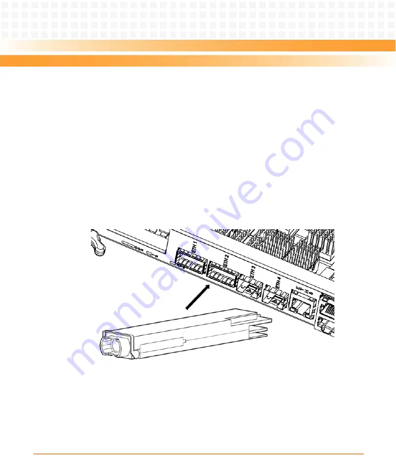
2.9.1
Installing QSFP+ transceiver modules
Procedure
Before proceeding wit h the installation, make sure that you are working in an ESD-safe
environment or wearing an ESD wrist strap or ESD shoes.
1. Remove the QSFP+ transceiver module from its protective packaging. Make sure that it is
the correct model and build for your system.
2. If you are using an optical QSFP+ transceiver, remove the optical bore dust plug and set it
aside.
3. Align the QSFP+ transceiver to the front of the module’s transceiver socket opening. Slide it
carefully into the socket until the QSFP+ transceiver connects with the socket electrical
connector.
For QSFP+ transceivers with a bail-clasp latch, keep it aligned in a vertical position.
For QSFP+ transceivers with a pull-tab, make sure that the identifier label is on top.
StockCheck.com
Содержание 6806800M67H
Страница 10: ...ATCA F140 Installation and Use 6806800M67H 10 List of Figures S t o c k C h e c k c o m ...
Страница 16: ...ATCA F140 Installation and Use 6806800M67H About this Manual 16 About this Manual S t o c k C h e c k c o m ...
Страница 100: ...Functional Description ATCA F140 Installation and Use 6806800M67H 100 S t o c k C h e c k c o m ...
Страница 138: ...Index ATCA F140 Installation and Use 6806800M67H 138 S t o c k C h e c k c o m ...
Страница 139: ...S t o c k C h e c k c o m ...


