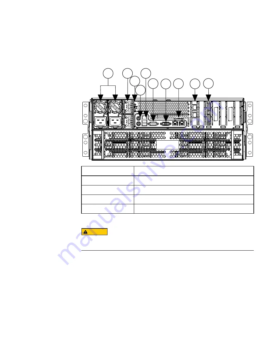
background image

Back panel

The back panel provides connections for power, network access, and serial
communication, as well as access to the backup batteries and power supplies.

3

2

1

5

6

8

9

10

4

7

1. Power supplies

6. Serial port

2. Batteries

7. VGA port

3. Power switch

8. 1 GigE external network ports

4. PS/2 ports

9. 1 GigE or 10 GigE external network ports

5. USB ports

10. InfiniBand internal network ports

CAUTION

Only trained EMC Isilon personnel should connect to the node with the PS/2, USB or VGA
ports. For direct access to the node, connect to the serial port.

LEDs

Do not rely on LEDs to determine the health of a node or node component. If any
hardware component is in an error state, identify and troubleshoot the error through
OneFS events and alerts. The behavior of the lights can change after a firmware update
and might not accurately reflect the health of a node.

Connect the internal cluster network

The InfiniBand cable connects the node to the cluster's internal network so the node can
communicate with the other nodes in the cluster.
Procedure

1. With an InfiniBand cable, connect the int-a port to the network switch for the Internal

A network.

Installation Guide

10

NL400


Installation Guide

Содержание Isilon NL400

Страница 1: ...d verify components 2 l Install the node in a rack 3 l Install the drives in the node 6 l Install the front panel 9 l Back panel 10 l Connect the internal cluster network 10 l Connect the external cli...

Страница 2: ...teps provided in this document to ensure compatibility with the cluster If you are performing this procedure with a node containing SEDs the node might take up to two hours longer to join the cluster...

Страница 3: ...ed components Four 8 32 0 75 inch knurled slide rail mounting screws Secures the slide rails to the rack cabinet Eight 8 32 0 25 inch shoulder alignment pins Use only for a pre threaded rack cabinet E...

Страница 4: ...mbled step alignment pins in the ends of the outer rails with the proper shoulder alignment pins Mount the outer rails Mount the outer rails in the rack cabinet Procedure 1 Adjust the outer rail rear...

Страница 5: ...y extend each intermediate rail until the rail locks into place 1 2 1 Inner Slide Rail 2 Intermediate Slide Rail 2 Keep the node level with the rails and align the ends of the inner rails with the end...

Страница 6: ...lead to severe injury when the node is pulled for future maintenance Install the drives in the node After the node is secured in the rack install the drives in the node There are 36 drive bays that yo...

Страница 7: ...eated will not be recognized when the node starts and a red light will appear below the drive To avoid this error run your finger across all the installed drives to ensure that they are seated evenly...

Страница 8: ...ar EMI shield 5 Insert and lock drives into the back bays until they are full 1 2 3 1 Rear EMI shield 2 Locking handle 3 Drive bay 6 Replace the rear EMI shield Installation Guide 8 NL400 Installation...

Страница 9: ...ays status information You can use the keypad and LCD to perform basic configuration tasks Procedure 1 Install the front panel assembly by aligning the front panel with the front of the node and then...

Страница 10: ...irect access to the node connect to the serial port LEDs Do not rely on LEDs to determine the health of a node or node component If any hardware component is in an error state identify and troubleshoo...

Страница 11: ...the node to the switch for the external network For additional 1 Gb connections use the ext 2 port CAUTION You must connect the 1 Gb ext 1 port to the external network even if you were planning on on...

Страница 12: ...power is present Note Both power supplies must be connected Operating a node using only one power supply for an extended period will shorten the life of the power supply If the installation site has...

Страница 13: ...e mode is incompatible with Isilon for vCenter VMware vSphere API for Storage Awareness VASA and the VMware vSphere API for Array Integration VAAI NAS Plug In for Isilon Connect to the node using a se...

Страница 14: ...le you to disable SmartLock compliance mode This is the last opportunity to back out of compliance mode without reformatting the node 2 Follow the prompts to configure the node For new clusters the fo...

Страница 15: ...You can configure the external network with IPv6 addresses by entering an integer less than 128 for the netmask value The standard external netmask value for IPv6 addresses is 64 If you enter a netma...

Страница 16: ...ing menus The LCD screen will be dark until you activate it To activate the LCD screen and view the menu press the square selection button You can press the right arrow button to move to the next leve...

Страница 17: ...the node with the right and left navigation buttons You can view the drives in other nodes in the cluster with the up and down navigation buttons The node you are viewing will display above the drive...

Страница 18: ...can press the left navigation button to back out of this menu without shutting down or rebooting Update the install database After all work is complete update the install database Procedure 1 Browse...

Страница 19: ...and user contributed content into topic areas making it easy to find content about subjects that interest you Support for IsilonSD Edge If you are running a free version of IsilonSD Edge community sup...

Страница 20: ...ublication and specifically disclaims implied warranties of merchantability or fitness for a particular purpose Use copying and distribution of any EMC software described in this publication requires...

Отзывы: