Eltako – The System in the Building – Operating manual for Series 14 RS485 bus DIN rail mounted devices
5
Startup
1. Mounting in the distribution panel: The arrangement order of the devices on the DIN mounting rail is freely definable. We advise
you to start on the left-hand side with the FAM14 or FTS14KS. At a load of greater than 50% of the rated power of 8W, use the
DS14 spacer to adjust an air gap of half a pitch unit on the left-hand side.
Use the enclosed 4-pole jumpers to cross-wire the bus and the power supply.
Only fit the jumpers after completing all the
electrical connections to the devices!
The torque exerted when tightening the screw terminal may displace the devices on the
rail slightly to one side. This force is transferred to the jumpers and could damage the internal contacts permanently.
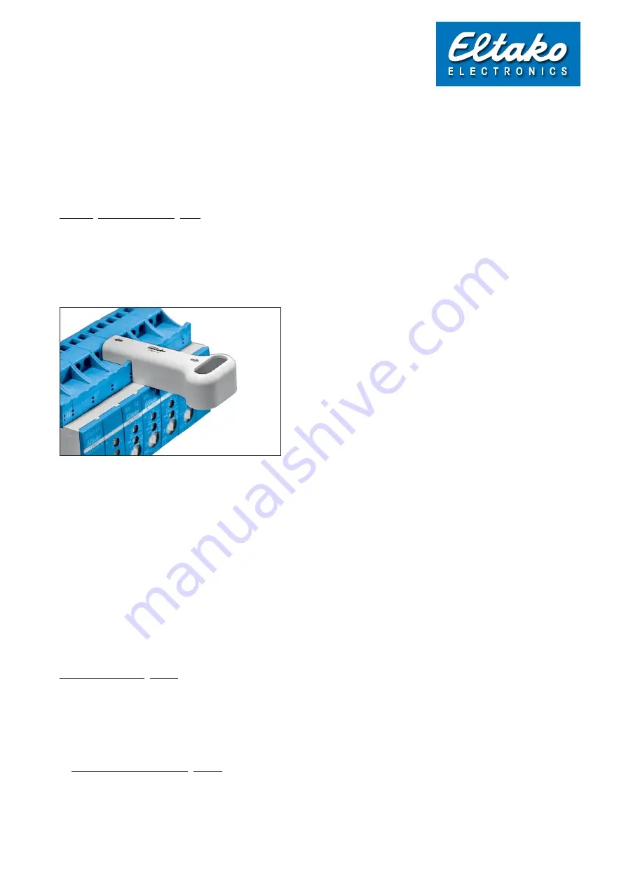
When inserting or removing the jumpers, only use the SMW14 jumper tool and move it vertically to the rail.
If you fit an FUD14 dimmer equal to or greater than 200W, use DS14 spacers to ensure there is an air gap to the devices mounted
on either side.
The bus connection to the devices across several rails is provided by the flexible BBV14 bus connector. The connection starts from
the last device on the right to the first device on the left on the next rail. Alternatively, you can use an FBA14 bus coupler. If other
devices are placed in a different distribution panel, the wiring can be extended there in the form of a bus. When the Hold wire
is also routed across several levels as well as an RSA/RSB, a GND wire must also be routed. A screened telecommunication
cable, or even better a CAT7 cable, is urgently required to connect the two distribution panels. Plug in the second terminal
resistor supplied with the FAM14 or FTS14KS to the final actuator.
All HOLD terminals from the devices on the bus must be connected together. Make sure that the GND potential of all associated
bus groups (e.g. with additional UVs) are connected together. The bus communication (regulation of the bus access, against
collision) will only work correctly if this connections are done.
Several FEM devices in a SUB-bus must be wired using a line in the form of a chain, as specified for RS485 bus systems. A
star-shaped wiring topology with one line per FEM is not permitted. The jumper must be plugged in a different position for each
of the three FEM wireless receiver modules.
Before issuing addresses, check the bus and all its jumpers using a measuring instrument as described in Chapter 6.
2. Device address assignment: Before startup, one of the 126 available device addresses should be assigned to every device.
Assigning a device address is recommended in all cases. Only then can you use the PCT14 software to carry out readout,
change and save operations. Without a device address the following devices cannot be taught-in to the actuators in the GFVS
Visualisation software: FSU14, FMSR14, F3Z14D, FSDG14, FWZ14, FWG14MS, DSZ14!
Please proceed carefully when assigning addresses to avoid issuing an address twice. Otherwise the addresses cannot be
read out by the PCT14 software!
See Point B) below for the safest way to assign addresses using the PCT14 software.
A) Manual device address assignment: Turn the BA operating mode rotary switch on the FAM14 or FTS14KS to Pos. 1. Its LED
lights up red. Turn the middle rotary switch of only one actuator at a time to LRN. Its LED flashes at a low rate (Caution: on the
FSR14, FAE14 and F4HK14 the lower rotary switch must also be set to the required channel). After several seconds, an address
is assigned; then the LED on the FAM14 or FTS14KS lights up for 5 seconds. The next device can only be addressed after the
LED switches back to red. Multi-channel actuators automatically receive consecutive addresses for all channels when addresses
are assigned.
3. Startup


