Technical Manual Cold Storage Controller EVP 3150-1 and EVP 3150-2
Page 16
Installation / Start-Up
Upon applying voltage to the controller, after a few seconds the display
shows the parameter which is selected as permanent display or an actual
error code.
Start-up sequence
• Assign inputs/outputs to functions (see example on page 3)
• Select type of used temperature sensors ("
P35
", Mode Page),
use TF 501 types for EEx-valves.
• Correct the displayed temperature values if necessary
("
P31
"-"
P34
", Mode Page).
• Set date and time ("
P81
"-"
P87
", Mode Page)
• Set defrost mode ("
d02
", Defrost Page)
• Set fan mode "
d01
" and "
P02
"
• Set cooling mode "
P03
" (Mode Page)
• See page 9 for parameterization of the pressure transmitter inputs
These are the most important steps for the basic configuration of the controller.
Upon that, adapt the other parameters like temperature setpoint, hysteresis,
delay times.... Refer to the previous chapters in this manual.
Start-up in a data network
• Set the address of the controller ("
P90
", Mode Page)
• Upload parameters from PC to controller
The EVP offers several status messages, which enables you to check the
states of inputs and outputs:
• "
L50
", value of the analogue output
• "
L60
", state of the digital inputs DI1 and DI2
• "
L61
", state of the relays
Sensor positions for EEx-Valve Control,
Pressure Transmitter / Temperature Sensor Method
The pressure transmitter must be mounted at the suction pipe, at a position
where no pressure decrease can affect the measuring. The best place is
close to the evaporator. If there are several evaporators, select a position
from where the distance to all evaporators is as short as possible.
Selection of Pressure Transmitter
To detect a pressure transmitter malfunction, the signal voltage input is
scalable. So you can use e.g. transmitters with an 2...10V output which
makes it easier to recognize a malfunction.
Number of controllers working with the same pressure
transmitter
The input resistance of the pressure transmitter input is 80 kOhm. Several
inputs can be connected in parallel, but the resulting resistance must not
fall below the minimum specifications of the used pressure transmitter.
In practise, up to 10 controllers mostly work trouble-free.
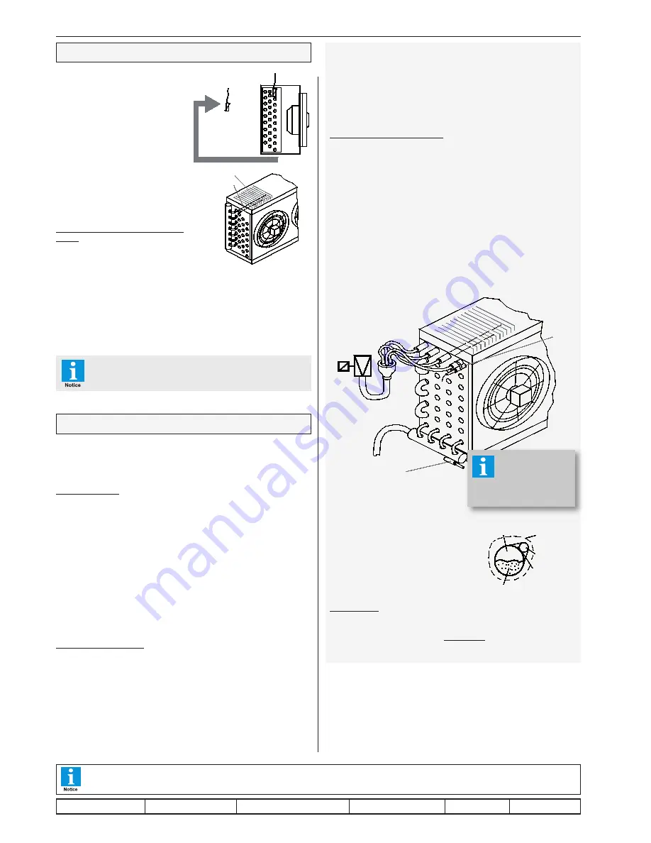
Sensor positions for EEx-Valve control,
Temperature Sensors Method
*
= alternative positions for Outlet-Sensor
Please care for a good isolation
by foamed material, so that none
of the sensors get contact with
the airflow.
Pipe mounting
Most expedient is it to use
cable fixers
, some thermal conduction silico-
ne cares for a good thermal flow.
Metallic fixers with high mass are not qualified.
Sensor Positions
Sensor positions are not critical in stan-
dard applications. The
control sensor
or
alarm sensor
has to be fixed behind
the evaporator (air-inlet) or at a repre-
sentative place in the chamber, but not
in the air outlet.
The second sensor (
defrost term-inati-
on sensor, evaporator sensor
) should
be assembled in the contact pipe or
within the fins of the evaporator. A good
thermal exchange to the fins is important.
It should be placed at the position where
the ice remains the longest time while
a defrost cycle.
Sensors for intelligent (adaptive)
defrost
To detect icing the EVP doesn't need
additional sensors. The control sensor
and the defrost (evap.) sensor are suf-
ficient. Please note that the emergency
defrost mode is not able to prevent ice-
clusters or slow glacieration in case of a
incorrect sensor position. If ice-clusters
appear, the defrost sensor must be
placed at this position.
After start-up, Please check the position of the
evaporator sensors accurately!!
This manual, which is part of the product, has been set up with care and our best knowledge, but mistakes are still possible. Technical details
can be changed without notice, especially the software. Please note that the described functions are only valid for units containing the software
with the version-number shown on page 1 of this manual. Units with an other version number may work a little bit different.
evap sensor
control sensor
airflow
fins
contact-
pipe
*
*
*
pipe
distributor
EEx-valve
outlet
sensor
inlet
sensor
foam Isolation
sensor
thermal
conduction
silicone
liquid
gaseous
refrigerant in evaporator pipe
For more infor-
mation about
Electronic Ex-
pansion Valves
see page 9 !
set up: 26.6.17, tkd/jr
checked: 26.6.17, ek/jk approved: 26.6.17, mv/sha
transl.(E): ...................... transl()................ corr.


