background image

16

English

For the design of the safety system to conform to engineer standards, the plant / machine 

must be professionally inspected at appropriate intervals for proper function. The inspection 

must be documented in such a way as to be comprehensible at all times.
The manufacturer assumes no liability in the event of non-observance or intentional abuse.

2. General safety regulations and protective measures 

•  The manufacturer and users of the plant / machine on which the protection is being used are responsible 

for implementing and following all applicable safety regulations and rules.

•  When used in conjunction with the higher-order controller, the protection guarantees functional safety, 

but not the safety of the entire plant / machine. The safety of the entire plant / machine must, therefore, 

be assessed in accordance with machinery directive 2006/42/EC or appropriate product norm before 

using the device. 

•  The operating instructions must always be available at the place of installation of the protection. They 

must be read thoroughly and observed by all persons involved in the operation, maintenance and servicing 

of the protection.

•  The protection must only be installed and commissioned by professionals familiar with these operating 

instructions and the applicable operational safety and accident prevention regulations. All of the instruc-

tions provided in these operating instructions must be observed and followed. All electrical work must 

only be performed by skilled electricians. 

•  All electrical work must only be performed by skilled electricians. All relevant electrical engineering and 

Employer‘s Liability Insurance Association safety regulations must be observed.

•  During work on the switching unit, it is to be switched to zero potential, checked to ensure that it is at 

zero potential and protected against being restarted.

•  The switching unit does not contain any components that require servicing by the user. Unauthorised con-

versions and repairs made to the switching unit will void all guarantees and the manufacturer’s liability.

•  Auxiliary outputs must not perform any safety-related functions. They are not one-fault safe and do not 

undergo a test.

Safety Relay

Содержание 39-726

Страница 1: ...t Seite 3 14 Manuel d utilisation Validit voir la derni re page ELMON rail 39 726 Relais de s curit Operating Manual see last page for validity ELMON rail 39 726 Safety Relay Page 15 26 Page 27 38 En...

Страница 2: ...suppl mentaires Componenti ausiliari Bijkomende componenten Funktionspr fung Functional test Contr le de fonction Controllo funzionale Functiecontrole Sicherheitssensoren reagieren auf Bet tigung Saf...

Страница 3: ...ausgang unverz gert RLU 8 7 4 Meldeausgang unverz gert blinkend RLU 9 7 5 Meldeausgang verz gert RL 9 8 Mechanische Befestigung 9 9 Elektrischer Anschluss 10 9 1 Anschluss der Versorgungsspannung 10 9...

Страница 4: ...muss st ndig am Einsatzort der Schutzeinrichtung verf gbar sein Sie ist von jeder Person die mit der Bedienung Wartung oder Instandhaltung der Schutzeinrichtung beauftragt wird gr ndlich zu lesen und...

Страница 5: ...ien Schaltkontakten sind verf gbar Eine Bet tigung der Signalgeber bewirkt eine Reaktion des Meldeausganges entsprechend der DIP Schalter Konfiguration Die Meldeausg nge d rfen keine sicherheitsgerich...

Страница 6: ...gabe vom Hersteller 5 Anwendungsbeispiel Schaltbild im spannungslosen Zustand Sensor nicht bet tigt Der Melderelais Ausgang dient zur Visualisierung des Schaltzustandes der Sicherheitskontaktleiste 5...

Страница 7: ...o wird ber die LED Power der Betriebszustand angezeigt an Bei Ausgabe einer Fehlermeldung gibt die Anzahl der ausgegebenen Pulse den Fehler an Pulse Fehlermeldung 1 Spannungsversorgung au erhalb des g...

Страница 8: ...r ckt Nach Beseitigung einer St rung eines Signalgeberstromkreises oder nach Spannungsausfall gibt das Schalt ger t den Ausgang automatisch wieder frei 7 2 Fehlerselbsthaltung manueller Reset S11 S12...

Страница 9: ...3 s 8 Mechanische Befestigung Das Schaltger t muss fachgerecht befestigt werden In einem staub und feuchtigkeitsgesch tztem Schaltschrank oder Geh use F r den Einsatz in einer Umgebung mit Verschmutz...

Страница 10: ...n die einzelnen Signalgeber entsprechend Bild 1 in Serie geschaltet Sicherheitskontaktleiste SENTIR edge Es k nnen maximal 5 SENTIR edge in Serie geschaltet werden Die maximale Gesamtl nge der SENTIR...

Страница 11: ...ammenbrechen kann z B durch kapazitive Elemente Eine bergeordnete Steuerung sollte die Zust nde des Ausgangssignals nur bewerten wenn der Pegel f r 5ms ansteht Damit wird vermieden dass die Pulse vom...

Страница 12: ...enderVersorgungsspannungdarfnurdiegr neLEDleuchten BeiAufleuch ten einer der roten LEDs ist ein Fehler im System vorhanden der sich mit Hilfe der LED eingrenzen l sst Die gelben LED s f r die Meldeaus...

Страница 13: ...m 2 A AC DC Mechanische Lebensdauer 5 x 10⁶ Bet tigungen Schaltzeiten Meldeausgang RL Funktion Einschaltverz gerung 0 5 s 0 2 s Ausschaltverz gerung 3 s 1 s Bei der RLU Funktion schaltet der Meldeausg...

Страница 14: ...ndlegenden Sicherheits und Gesundheitsanforderungen der nach folgenden EG Richtlinien entspricht EG Maschinenrichtlinie 2006 42 EG EN ISO 13849 1 2008 EN ISO 13849 2 2008 EN 61000 6 2 2005 EN 61000 6...

Страница 15: ...uxiliary output undelayed flashing RLU 21 7 5 Auxiliary output delayed RL 21 8 Mechanical mounting 21 9 Electrical connection 22 9 1 Connecting the supply voltage 22 9 2 Connecting the sensor 22 9 3 C...

Страница 16: ...f the protection They must be read thoroughly and observed by all persons involved in the operation maintenance and servicing of the protection The protection must only be installed and commissioned b...

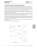
Страница 17: ...ply voltage Two auxiliary outputs with potential free switching contacts are available Actuation of the sensors triggers a reaction by the auxiliary output according to the DIP switch configuration Th...

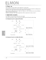
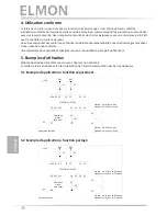
Страница 18: ...agram in zero potential state Sensor not actuated The auxiliary relay output is used for visualising the switching state of the safety contact edge 5 1 Example of use for separated function 5 2 Exampl...

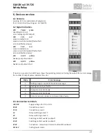
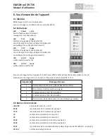
Страница 19: ...ut switched If no error is present then LED Power shows the operating state on During the output of an error message the number of output pulses indicates the error Pulse Error message 1 Voltage suppl...

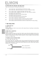
Страница 20: ...reset S11 S12 bridged Following rectification of a fault in a sensor circuit or after a power failure the switching unit automatically re enables the output 7 2 Error lock manual rese S11 S12 not con...

Страница 21: ...0 5 s 3 s 8 Mechanical mounting The switching unit must be professionally mounted In a dust and moisture protected switching cabinet or housing Installation in a Pollution Degree 2 environment With a...

Страница 22: ...individual sensors are connected in series according to figure 1 Safety edges SENTIR edge Up to five SENTIR edge may be connected in series The maximum total length oft the SENTIR edge shall not excee...

Страница 23: ...of activation the voltage cannot break down e g by means of capacitive elements A primary controller should only evaluate the states of the output signal if the level is sustained for 5 ms This preven...

Страница 24: ...LED may illuminate if the supply voltage has been correctly connected If one of the red LEDs illuminate there is an error in the system which can be pinpointed with the aid of the LED The yellow LEDs...

Страница 25: ...voltage 50 V AC DC Max switching current 2 A AC DC Mechanical life time 5 x 10⁶ actuations Switching times auxillary output RL function Switching on delay 0 5 s 0 2 s Switching off delay 3 s 1 s With...

Страница 26: ...ectives listed below on account of its design and construction as does the version brought to market by us Machinery directive 2006 42 EC EN ISO 13849 1 2008 EN ISO 13849 2 2008 EN 61000 6 2 2005 EN 6...

Страница 27: ...mm diate RLU 32 7 4 Sortie auxiliaire imm diate clignotante RLU 33 7 5 Sortie auxiliaire retard e RL 33 8 Fixation m canique 33 9 Raccordement lectrique 34 9 1 Raccordement de la tension d alimentatio...

Страница 28: ...du dispositif de protection Il doit tre minutieusement lu et appliqu par toute personne charg e de l emploi de l entretien et de la maintenance du dispositif de protection Seul le personnel sp cialis...

Страница 29: ...avec les contacts de commutation libres sont disponibles Un actionnement de l metteur de signaux provoque une r action de la sortie auxiliaire selon la configuration des commutateurs DIP Les sorties a...

Страница 30: ...icant 5 Exemples d utilisation Sch ma de principe dans l tat sans courant Capteur non actionn La sortie de relais auxiliaire sert la visualisation de l tat de commutation des barres palpeuses 5 1 Exem...

Страница 31: ...ionnement allum Lors de l dition d un message d erreur le nombre d impulsions mises identifie l erreur Impulsions Message d erreur 1 Alimentation en tension en dehors des limites valides 2 Erreur dans...

Страница 32: ...d op ration 7 1 RAZ automatique S11 S12 pont s Apr s limination d un incident d un circuit de signal ou apr s une panne de courant le relais de s curit lib re automatiquement la sortie 7 2 Verrouillag...

Страница 33: ...ais de s curit doit tre fix correctement dans une armoire lectrique ou un bo tier prot g contre la poussi re et l humidit pour une utilisation en environnement de degr de pollution 2 d indice de prote...

Страница 34: ...s sur l entr e d metteur de signaux Pour cela les metteurs de signaux individuels sont mont s en s rie comme illustr figure 1 Barre palpeuse SENTIR edge Il est possible de monter au plus 5 SENTIR edge...

Страница 35: ...s annuler p ex l ments capacitifs Une commande sup rieure ne doit valuer les tats du signal de sortie que si le niveau est appliqu pendant 5 ms Cela permet d viter que les impulsions de l auto test d...

Страница 36: ...ise sous tension seule la LED verte doit briller Si une des LED rouges s allume il y a une erreur dans le syst me que la LED allum e permet de localiser Les LED jaunes pour les sorties de signalisatio...

Страница 37: ...rant de comm max 2 A AC DC Dur e de vie m canique 5 x 10⁶ actionnements Temps de commutation de la sortie auxiliaire Fonction RL Retard l enclenchement 0 5 s 0 2 s Retard au d clenchement 3 s 1 s Dans...

Страница 38: ...ar nos soins r pondent aux exigences de base pour la s curit et la sant des directives CE suivantes Directive machines 2006 42 CE EN ISO 13849 1 2008 EN ISO 13849 2 2008 EN 61000 6 2 2005 EN 61000 6 3...

Страница 39: ...39 Notizen Notes Notes...

Страница 40: ...al is valid for the following versions V 1 0 Deutsch English Antriebs und Steuerungstechnik Hansastra e 52 D 59557 Lippstadt Tel 49 2941 9793 0 Fax 49 0 2941 9793 142 www asosafety com e mail info aso...

Отзывы: