18
4. Proper use
The switching unit can only fulfil its safety-related task if used properly.
The switching unit is intended to be used as protection in combination with safety contact mats, safety bumpers
and safety contact edges with 8.2 kΩ resistor for standby-current monitoring.
Any uses above and beyond these uses constitute improper use. The manufacturer assumes no liability for
damages arising from improper use.
The device may only be used in special applications with the manufacturer’s express consent.
5. Application examples
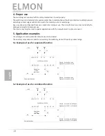
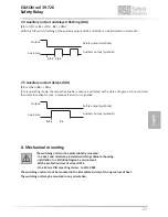
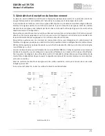
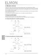
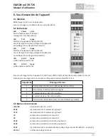
Circuit diagram in zero-potential state. Sensor not actuated.
The auxiliary relay output is used for visualising the switching state of the safety contact edge.
5.1 Example of use for separated function
5.2 Example of use for combined function
English
Safety Relay
24 32 42
14
S12
S11
0V
+24V X1 X2
Y2 Y2
31 41
K1
K2
0V
+24V
8k2
8k2
S1
S2
K1
K2
Closed:
Opened:
Closed:
Opened:
Switch S2 open
Switch S2 closed
Switch S1 open
Switch S1 closed
ELMON rail 39-726
Separated function
Operation
mode:
auto reset
24 32 42
14
S12
S11
0V
+24V X1 X2
Y2 Y2
31 41
K1
K2
0V
+24V
8k2
8k2
S1
S2
K1
K2
Closed:
Opened:
Closed:
Opened:
Switch S1 and S2 open
Switch S1 or S2 closed
Switch S1 and S2 open
Switch S1 or S2 closed
ELMON rail 39-726
Shared function
Operation
mode:
auto reset
Содержание 39-726
Страница 39: ...39 Notizen Notes Notes...


