background image

135

135

OPERA

T

ION OF THIS 

CAMERA

ENGLISH

1.

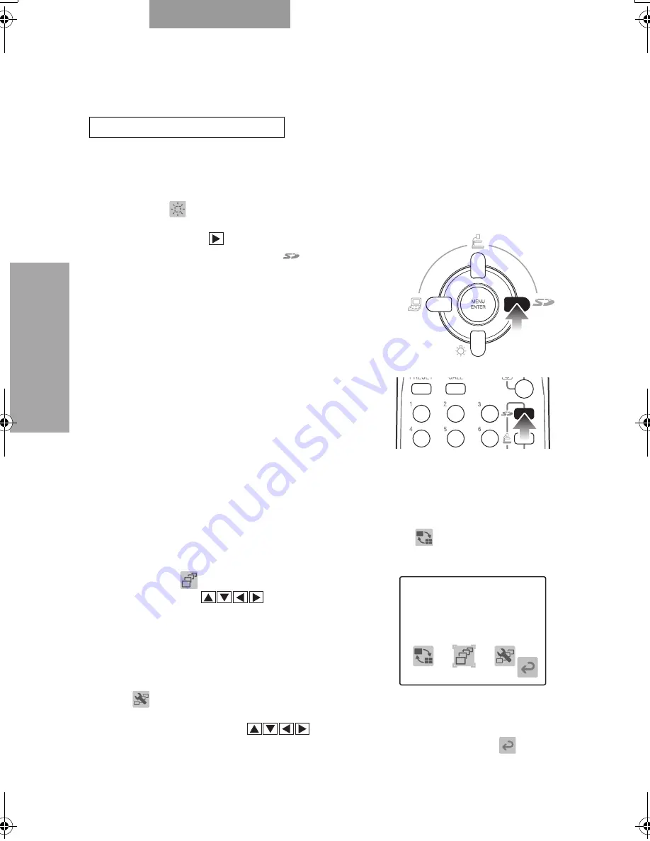
When the OSD menu is in display, hide the OSD menu by operating
the front operating panel or repeatedly pressing the [BACK] button on
the wireless remote control.

When [

HIDE MENU] is ON, cancel it.

2.

Press the [

] button on the front

operating panel or the [

] button on

the wireless remote control to switch the
mode to the SD mode.

One image saved on the SD card is
displayed. [SINGLE]

3.

Press the [MENU/ENTER] button on the front operating panel or
wireless remote control.

The OSD SD Split screen menu appears.
When the OSD SD Single menu appears, select [

DISPLAY]

[3x3] or

[4x4].

4.

Select [

START SLIDE SHOW] by

using the [

] buttons on the

front operating panel or wireless remote
control.

The slide show starts.
To set the slide show, go to the OSD SD
Slide Show Setting menu by pressing
[

SLIDE SHOW SETTING].

5.

Press any of the [

] buttons or [MENU/ENTER] button on

the front operating panel or wireless remote control or the [

BACK]

button on the wireless remote control.

The slide show stops.

For Performing Slide Show

OSD SD Split screen Menu

書画カメラ P30S.book  135 ページ  2008年1月24日 木曜日 午後6時38分

Содержание Document Camera P30S

Страница 1: ...ijſőĹIJ Deutch P000 P000 Français P000 P000 DOCUMENT CAMERA P30S INSTRUCTION MANUAL English P80 P157 80 Please read this instruction manual carefully before using this product and keep it for future reference ...

Страница 2: ...81 ...

Страница 3: ...ng serious injury to a child or adult and serious damage to the product Use only with a cart stand tripod bracket or table recommended by the manufacturer or sold with the product Any mounting of the product should follow the manufacturer s instructions and should use a mounting accessory recommended by the manufacturer Ventilation Slots and openings in the cabinet are provided for ventilation and...

Страница 4: ... them paying particular attention to cords at plugs convenience receptacles and the point where they exit from the product Lightning For added protection for this product during a lightning storm or when it is left unattended and unused for long periods of time unplug it from the wall outlet and disconnect the antenna or cable system This will prevent damage to the product due to lightning and pow...

Страница 5: ...r hazards Safety Check Upon completion of any service or repairs to this product ask the service technician to perform safety checks to determine that the product is in proper operating condition Heat The product should be situated away from heat sources such as radiators heat registers stoves or other products including amplifiers that produce heat This product includes a Fluorescent Lamps compon...

Страница 6: ...limits for a Class A digital device pursuant to Part 15 of the FCC Rules These limits are designed to provide reasonable protection against harmful interference when the equipment is operated in a commercial environment This equipment generates uses and can radiate radio frequency energy and if not installed and used in accordance with the instruction manual may cause harmful interference to radio...

Страница 7: ...he lamp column while your finger is being placed between the camera column and the lamp column Otherwise your finger may be pinched and injured Use a soft dry cloth for cleaning Do not use any volatile solvent such as thinner or benzine Do not directly point the camera lens into the sun or the camera may be damaged Caring for the batteries If this camera system is not used for a long time take out...

Страница 8: ...not look into the lamp LED part directly at close range It may damage your eyes When this Camera is used longer than the warranty period some parts may deteriorate in performance or quality due to the expiration of the service life In this case we will replace such parts with payment Consult the sales outlet from whom you have purchased this Camera or our branch or sales office nearest your locati...

Страница 9: ...e Camera 111 OPERATION OF THIS CAMERA 112 Turning ON OFF Power Supply 112 Basic Operation of OSD 113 Turning ON OFF Lamp 115 Adjusting Zoom 117 Switching Video 118 Adjusting Focus 119 Adjusting Brightness 121 Adjusting White Balance 123 Presetting and Calling 125 Using SD Card Option 126 Using Bundled Software 141 Shooting off the Stage 144 Presentation Using Films 145 ABOUT RS 232C 146 Connecting...

Страница 10: ... Wireless remote control sensor unit Front operating panel P 91 LCD panel Stage Side panel SD USB P 93 Wireless remote control P 94 Wireless remote control holder P 104 Slide shooting adapter P 145 Note Do not move the camera column or the lamp column while your finger is being placed between the camera column and the lamp column Otherwise your finger may be pinched and injured ӱ Ӵ ӵ Ӷ ӷ ӹ Ӹ Ӻ ӽ Ӿ...

Страница 11: ... page Wireless remote control sensor unit Rear panel P 92 Cord cover Note The wireless remote control sensor unit is also located on the front side When plugging unplugging the cord open the cord cover When carrying the Camera do not hold on to the cord cover Ԁ ԁ ӿ ...

Страница 12: ...o to the camera video and the color of the front operating panel LED to blue P 118 down button To switch the ON OFF of the lamp P 115 right button To switch the mode of the output video to the SD mode and the color of the front operating panel LED to orange P 118 left button To switch the output video to the RGB IN video and the color of the front operating panel LED to pink P 118 SD Mode right bu...

Страница 13: ... Analog RGB Input Terminal To output the input video from the analog RGB output terminal when RGB IN is selected in the Display mode P 109 RS 232C RS 232C Terminal To control the main body from the PC through the connected RS 232C cable P 146 12VDC IN Power Socket A plug in receptable for the AC adapter P 107 DIP Switch To execute the following switching A key Invalid B key Invalid C key To switch...

Страница 14: ...o transfer or main unit by using the bundled utility software on the Utility Software CD ROM through the connected PC P 138 SD Card Slot To insert the SD card To remove SD card push the SD card again and the SD card will be released P 126 Main Switch To turn ON OFF the power supply to the main unit P 112 Ӳ ӱ ӳ ...

Страница 15: ...94 ENGLISH OUTLINE OF THIS CAMERA Wireless Remote Control ӱ Ӳ ӳ Ӵ Ӷ ӷ ӵ Ӷ Ӹ ӹ Ӻ ӻ Ӽ ӽ Ӿ Ԅ ԃ Ԃ ԁ Ԁ ӿ ijIJ ijIJ ijij ijij ijĴ ijĴ ijĵ ijĵ ijĶ ijĶ ijķ ijķ ...

Страница 16: ...GHT NESS NORMAL To reset the auto brightness adjustment degree to the normal status P 121 BRIGHT To brighten the camera video P 121 DARK To darken the camera video P 121 ZOOM TELE SCOPIC To set the zoom to the TELESCOPIC side P 117 WIDE ANGLE To set the zoom to the WIDE ANGLE side P 117 CAPTURE To save the image on the SD card P 127 SD MODE To switch the mode of the output video to the SD mode P 1...

Страница 17: ...o IMAGE ROTATION To rotate the camera video by 180º P 144 FOCUS NEAR To move the focus to the near side P 119 FAR To move the focus to the far side P 119 AF Auto Focus To bring the Camera into focus automatically P 119 LAMP To switch the ON OFF of the lamp P 115 Note It is impossible to add another processing to the video in pause ijIJ ijij ijĴ ijĵ ijĶ ijķ ...

Страница 18: ...o P 118 and the MENU ENTER button is pressed the OSD Main menu appears Icon Name Condition Selection item Function CAPTURE To save the image on the SD card TEXT To switch TEXT1 2 3 set in TEXT SETTING of the setting menu to sharpen the B W characters and lines Used for shooting the material e g document GRAPHICS To switch the mode to the Graphic mode to enhance the color object e g drawing photo S...

Страница 19: ...ith the level bar and darken the camera video with the level bar BRIGHT NESS MANUAL To brighten the camera video with the level bar and darken the camera video with the level bar WHITE BALANCE AUTO To set the white balance to the auto following ONE PUSH To set the white balance to the fix MANUAL To set the white balance so that R GAIN and B GAIN can be adjusted manually R GAIN WHITE BALANCE MANUAL...

Страница 20: ...RGB output to 1280x1024 XGA To switch the resolution of the DVI and analog RGB output to 1024x768 HD To switch the resolution of the DVI and analog RGB output to 1280x720 FLICKERLESS 60Hz To lower the fluorescent lamp flicker due to power frequency 50Hz USB MODE MASS STORAGE To transfer the data on the SD card set in this Camera to the USB connected PC APPLIC ATION To control this Camera from the ...

Страница 21: ...ay the image saved on the SD card in the split status 4x4 DELETE CURRENT Yes To delete the displayed image No To leave the displayed image undeleted If the image is locked the image cannot be deleted ALL Yes To delete all images No To leave all images undeleted When the image is locked the image cannot be deleted LOCK CURRENT Yes To lock the image to set the image protected from deletion No To lea...

Страница 22: ...tton on the wireless remote control is pressed the OSD SD Split screen menu icon appears DISPLAY SINGLE To display the image saved on the SD card in the unsplit status SINGLE 3x3 To display the image saved on the SD card in the split status 3x3 4x4 To display the image saved on the SD card in the split status 4x4 START SLIDE SHOW To start the slide show SLIDE SHOW SETTING To display the OSD Slide ...

Страница 23: ...0 SEC EFFECT LEFT TO RIGHT To set the image slide direction in the slide show LT TO RB RT TO LB NONE To set no visual effect in the slide show SELECT ALL To set the object to be displayed in the slide show to all displayable image saved on the SD card LOCKED ONLY To set the object to be displayed in the slide show only to the locked images saved on the SD card ORDER FORWARD To perform the slide sh...

Страница 24: ...narrowed and the laser beam from the wireless remote control may not be sensed depending on the surrounding circumstances e g sun light position adjacent to inverter fluorescent lamp In this case relocate the receiving side or shield the sun light or fluorescent lamp When setting the batteries remove the battery case cover by pushing the mark in the arrow direction on the back side of the wireless...

Страница 25: ... follows 1 Insert the tab of the wireless remote control holder into the slit of the rear side of the stage for latching 2 Lower the wireless remote control holder 3 Set the wireless remote control in the holder How to Attach Wireless Remote Control Holder Tab Slit Wireless remote control holder Wireless remote control ...

Страница 26: ...INE OF THIS CAMERA ENGLISH 1 Lift the camera column Simultaneously the lamp column rises 2 Turn the camera head 3 Move the lamp column and the lamp head to an appropriate position How to Set up the Camera ӱ Ӳ ӳ ...

Страница 27: ...he power supply to the Camera Note When using the Camera adjust the lamp column and the lamp head to the easy to work position beforehand When lifting or lowering the camera column and the lamp column be careful not to have your finger or the like pinched When shooting a transparent film place a white paper under the film This is applicable only to the black body type of the North American specifi...

Страница 28: ... unplug the power plug from the outlet beforehand When plugging unplugging the power plug the AC adapter and the video cable hold on to their cable connector plugs For the information of how to switch the output video refer to Switching Video P 118 For the information of how to switch the video output system refer to DIP Switch P 92 For Connecting AC Adapter Ӳ ӳ Ӵ ӵ Ӷ ӷ USB terminal ȆTo PC DVI OUT...

Страница 29: ... Input Terminal For Connecting to device having Analog RGB Input Terminal Note The display position of the screen may be displaced from the center of the screen In this case adjust the horizontal and vertical positions manually from the connected device Vertical stripes may appear on the LCD projector or the monitor screen In this case adjust the dot clock manually from the connected device The ve...

Страница 30: ...put terminal For Connecting to device having Analog RGB Output Terminal Signal allocation Terminal arrangement Pin No Name Pin No Name Pin No Name 1 Video signal Red 6 GND Red 11 GND 2 Video signal Green 7 GND Green 12 N C 3 Video signal Blue 8 GND Blue 13 Horizontal synchronization signal 4 N C 9 N C 14 Vertical synchronization signal 5 GND 10 GND 15 N C For Connecting to device having Composite ...

Страница 31: ...nput Terminal Note If the unit to be used is of Y C separate connector type a conversion adapter should be used For Connecting to PC with USB Cable Note The USB cable should preferably be of USB 2 0 complied If the USB cable is connected without turning OFF the power supply to the Camera and the PC beforehand the PC may not recognize the USB correctly Under the influence of the USB environment or ...

Страница 32: ...the video cable from the Camera Connecting of AC Adapter and Video Cable P 107 3 Turn the lamp head and the lamp column and fold them on the stage 4 Turn the camera head and the camera column and fold them How to Store The Camera Note When storing the Camera turn OFF the power supply to the Camera beforehand Ref ӱ Ӳ ӳ Ӵ ...

Страница 33: ... SWITCH switch The power supply to the Camera is turned OFF Turning ON OFF Power Supply For Turning ON Note When connecting the Camera to other device turn OFF the power supply to all device beforehand For Turning OFF Note Do not turn ON OFF the power supply to the Camera by plugging unplugging the AC adapter or power plug Even if instantaneous power failure occurs the main unit of the Camera may ...

Страница 34: ... the MENU ENTER button on the front operating panel or wireless remote control Basic Operation of OSD For Selecting and Deciding Icon For Selecting and Deciding Item MENU ENTER MENU ENTER δΗϋ δΗϋ MENU ENTER button MENU ENTER MENU ENTER δΗϋ δΗϋ MENU ENTER button To return the display of the OSD menu to the previous one ȁ button ऒ δΗϋ δΗϋ ȁ button ȁ button ષ δΗϋ δΗϋ ȁ button ȁ button ȁ button ષ δΗϋ ...

Страница 35: ...ess remote control For Adjusting Level Bar Front operating panel Wireless remote control To fix the level bar set value To return the display of the OSD menu to the previous one τασΨȜ τασΨȜ ୭ ષ ୭ ષ To increase the level bar set value To decrease the level bar set value To fix the level bar set value τασΨȜ τασΨȜ ୭ ષ ୭ ષ To increase the level bar set value To decrease the level bar set value Level b...

Страница 36: ...ote control When HIDE MENU is ON cancel it 2 Press the button on the front operating panel or the button on the wireless remote control 3 Each time the button on the front operating panel or the button on the wireless remote control is pressed the material lamp repeats turning ON and OFF Turning ON OFF Lamp Note Do not look into the lamp part It may damage your eyes The brightness of the lamp LED ...

Страница 37: ...ot be shot on the screen 2 Adjust the angle of the lamp head while watching the screen so that the illumination can be provided uniformly over the stage For Adjusting Illumination Position Note Depending on the illumination position the shadow of the camera column may appear on the screen ...

Страница 38: ...the zoom speed will be changed in 2 steps Adjusting Zoom Note The zoom magnification is available up to 16xfor the optical zoom and up to 4xfor the digital zoom When the digital zoom is in operation the image quality is degraded Within the digital zoom range the zoom speed stays constant When the digital zoom is in operation the screen can be scrolled by using the buttons on the wireless remote co...

Страница 39: ...nnected to the analog RGB input terminal RGB IN the output video from the analog RGB output terminal RGB OUT can be switched without any trouble to exchange the connection cable From the video output terminal VIDEO OUT and the DVI output terminal DVI OUT only the camera video is output and the RGB IN video cannot be output If the mode is switched to the SD mode when the SD card is not set in the C...

Страница 40: ...any part of the object e g 3D material 1 Press the AF button on the Camera The object is brought into focus automatically When the wireless remote control is used press the AF button 1 Press the NEAR button or FAR button on the wireless remote control The focus can be adjusted manually Adjusting Focus For Auto Focus Note When the NEAR button or FAR button on the wireless remote control is pressed ...

Страница 41: ... brought into focus in the auto focus In this case use the manual focus buttons NEAR and FAR on the wireless remote control Objects with a little difference between brightness and darkness contrast Objects with repeated fine patterns e g crossbars lattices Objects that are glittering reflecting intensive light or bright Objects with bright background or excessive contrast Objects whose images are ...

Страница 42: ...S AUTO from the OSD Setting menu by using the buttons on the front operating panel or wireless remote control 6 Select BRIGHTNESS SETTING ADJUST from the OSD Setting menu by using the buttons on the front operating panel or wireless remote control and set the level bar by using the buttons The degree of brightness for auto following can be adjusted Alternatively by pressing the and buttons in the ...

Страница 43: ... panel or wireless remote control 6 Select BRIGHTNESS SETTING from the OSD Setting menu by using the buttons on the front operating panel or wireless remote control and set the brightness by using the buttons so that it can be fixed to an intended level Alternatively by pressing the and buttons in the BRIGHTNESS item on the wireless remote control the degree of brightness can be adjusted For Adjus...

Страница 44: ...using the buttons on the front operating panel or wireless remote control and select an intended item AUTO To set the white balance to the auto following Used for adjusting the intensity of the white color of video automatically depending on the material condition ONE PUSH To set the white balance to the fix Used in case that the color balance of video is lost due to the material condition MANUAL ...

Страница 45: ... Select SETTINGS from the OSD Main menu by using the buttons on the front operating panel or wireless remote control The OSD Setting menu appears 5 Select WHITE BALANCE MANUAL from the OSD Setting menu by using the buttons on the front operating panel or wireless remote control 6 Select R GAIN or B GAIN from the OSD Setting menu by using the buttons on the front operating panel or wireless remote ...

Страница 46: ...on the wireless remote control is pressed within 4 sec the status saved in the selected memory No are called up When CALL FACTORY SETTING Yes are selected from the OSD Setting menu the functions that can be set in Presetting and Calling can be reset to the factory settings Presetting and Calling Note The status saved in each memory No can be retained even if the power supply to this Camera is turn...

Страница 47: ... the SD card may be broken Since the SD card is made up of components susceptible to static electricity the SD card may have false operation or its contents may be destroyed under the influence of static electricity Therefore treat the SD card with utmost care not to be affected by static electricity All image data that can be displayed on the Camera is only the image data saved in the Camera and ...

Страница 48: ... For Saving Images on SD Card Note Be sure to try shooting and confirm the normal saving of the image beforehand If the image saving is failed due to some trouble in this Camera or the SD card ELMO Co Ltd is not liable to the compensation for the loss of the image data The mark is displayed on the screen only when GUIDE has been set to ON on the OSD Setting menu If the SD card switch is set to wri...

Страница 49: ...n To switch the output video to the camera video button To switch the ON OFF of the lamp button To switch the output video to the RGB IN video button To display the next image saved on the SD card Screen Feed Forward MENU ENTER To display the OSD SD Single menu or the OSD SD Split screen menu The menu appears as per set in DISPLAY Operation of the wireless remote control in the SD mode To display ...

Страница 50: ...mode One image saved on the SD card is displayed SINGLE 3 Press the MENU ENTER button on the front operating panel or wireless remote control When the current settings are default the OSD SD Split screen menu appears When the OSD SD Split screen menu appears select DISPLAY SINGLE For Displaying OSD SD Single Menu Note To hide the icon of the OSD SD Single menu press HIDE MENU To redisplay the icon...

Страница 51: ...e mode to the SD mode One image saved on the SD card is displayed SINGLE 3 Press the MENU ENTER button on the front operating panel The OSD SD Split screen menu appears When the OSD SD Single menu appears select DISPLAY 3x3 or 4x4 For Displaying OSD SD Split screen Menu Note To hide the icon of the OSD SD Split screen menu press HIDE MENU To redisplay the icon press any of the buttons or MENU ENTE...

Страница 52: ...U is ON cancel it 2 Press the button on the front operating panel or the button on the wireless remote control to switch the mode to the SD mode One image saved on the SD card is displayed SINGLE 3 Press the MENU ENTER button on the front operating panel The menu appears as per set in DISPLAY When the OSD SD Split screen menu appears select DISPLAY SINGLE For Selecting Images on SD Card from OSD S...

Страница 53: ...cted Basic operation for image selection button To display the next image saved on the SD card Screen Feed Forward button To display the previous image saved on the SD card Screen Feed Backward button To return to the selection of the OSD SD Single menu icon MENU ENTER button To switch the split screen display to 3x3 or 4x4 and display the OSD SD Split screen menu OSD SD Single Menu ...

Страница 54: ...NU is ON cancel it 2 Press the button on the front operating panel or the button on the wireless remote control to switch the mode to the SD mode One image saved on the SD card is displayed 3 Press the MENU ENTER button on the front operating panel The menu appears as per set in DISPLAY When the OSD SD Single menu appears select DISPLAY 3x3 or 4x4 For Selecting Images on SD Card from OSD SD Split ...

Страница 55: ...he OSD SD Single menu When the cursor is on the top image area and the button is pressed the previous page is displayed When the cursor is on the top left image area and the button is pressed the previous page is displayed When the cursor is on the bottom right image area and the button is pressed the next page is displayed When the cursor is on the bottom image area and the button is pressed the ...

Страница 56: ...e MENU ENTER button on the front operating panel or wireless remote control The OSD SD Split screen menu appears When the OSD SD Single menu appears select DISPLAY 3x3 or 4x4 4 Select START SLIDE SHOW by using the buttons on the front operating panel or wireless remote control The slide show starts To set the slide show go to the OSD SD Slide Show Setting menu by pressing SLIDE SHOW SETTING 5 Pres...

Страница 57: ...ng panel or wireless remote control and select the image to be deleted For details of the operation for selecting the image saved on the SD card from the OSD SD Single menu refer to P 131 5 Select DELETE CURRENT Yes from the OSD SD Single menu by using the buttons on the front operating panel or wireless remote control The image in display is deleted However if the image is locked it cannot be del...

Страница 58: ...r the button on the wireless remote control to switch the mode to the SD mode One image saved on the SD card is displayed SINGLE 3 Press the MENU ENTER button on the front operating panel or wireless remote control The OSD SD Split screen menu appears When the OSD SD Single menu appears select DISPLAY 3x3 or 4x4 4 Select FORMAT MEDIA Yes by using the buttons on the front operating panel or wireles...

Страница 59: ... on the wireless remote control When HIDE MENU is ON cancel it For Importing Image from SD Card into PC through USB Cable Note The PC installed with the OS of Microsoft Windows2000 SP4 or newer XP SP2 or newer or Vista 32 bits is connectable For details of the USB mode refer to OSD Setting Menu P 98 Under the influence of the USB environment or peripheral units used by the PC image transfer may be...

Страница 60: ...rol to switch the output video to the camera video 3 Press the MENU ENTER button on the front operating panel or wireless remote control The OSD Main menu appears 4 Select SETTINGS from the OSD Main menu by using the buttons on the front operating panel or wireless remote control OSD The OSD Setting menu appears OSD Main Menu ...

Страница 61: ... and Play function of Windows For the second and subsequent connections the driver installation will not be displayed The image cannot be saved deleted locked or unlocked or the SD card cannot be formatted from the PC The image file cannot record the correct date and time When the power supply to the Camera is ON do not plug unplug the USB cable into from the Camera or malfunction will be caused t...

Страница 62: ...dware requirements of the PC to be connected and how to use the OS PC and link software refer to the installation manual of the Utility Software and HELP Folder on the CD ROM When the power supply to the Camera is ON do not plug unplug the USB cable into from the Camera or malfunction will be caused to the Camera It is recommendable that the USB cable to be used should be of USB 2 0 complied When ...

Страница 63: ...e BACK button on the wireless remote control When HIDE MENU is ON cancel it 2 Press the button on the front operating panel or the button on the wireless remote control to switch the output video to the camera video 3 Press the MENU ENTER button on the front operating panel or wireless remote control The OSD Main menu appears For Using Bundled Software ...

Страница 64: ...rs 5 S e l e c t U S B M O D E APPLICATION from the OSD Setting menu by using the buttons on the front operating panel or wireless remote control 6 Connect the USB cable to the PC The moving still image data can be transferred to the PC or the Camera can be controlled from the PC For Connecting to PC with USB Cable P 110 OSD Main Menu OSD Setting Menu APPLICATION MASS STORAGE Ref ...

Страница 65: ...gle 100mm 3 9 in from the zoom lens Shooting off the Stage For Shooting Forward and Backward from The Camera Note The manual rotation of the camera video output can be adjusted by selecting IMAGE ROTATION ON or OFF from the OSD Setting menu or by pressing the IMAGE ROTATION button on the wireless remote control For Shooting Wall or Landscape Note Do not fold the camera column without closing the c...

Страница 66: ...ttons on the wireless remote control 4 Adjust the focus Press the AF button on the camera head or wireless remote control to bring the camera into focus 5 Adjust the brightness If the screen is too bright or too dark adjust the brightness by selecting BRIGHTNESS SETTING from the OSD Setting menu or pressing the BRIGHTNESS or button on the wireless remote control Presentation Using Films Note Accor...

Страница 67: ...C control starts Connecting RS 232C For Setting up Note When using a commercial RS 232C cable make sure that the pins are connected as shown below To protect the Camera and the PC be sure to turn OFF the power switch of each unit before starting the connection work Note For the information how to set the communication mode of the RS 232C refer to the instruction manual of the PC How to connect the...

Страница 68: ...peration command is executed in ASCII code and transmitted in a set of 7 bytes as follows Response data format Camera PC All response data is transmitted in ASCII code corresponding to the parameters in the operation command table Specifications of RS 232C Data Format Specifications S T X E T X Command PC Camera ɨ ACK Data Parameter S T X Posi Nega Color B W Output video Display Flickerless E T X ...

Страница 69: ...uto focus AF 0 To perform the one shot auto focus Focus adjustment FO Near To adjust the focus Far 0 Stop Zoom adjustment ZO Tele To adjust the zoom Wide 0 Stop Iris adjustment IR Open To adjust the iris Close 0 Stop 1 Auto 2 Manual Lamp switching PL 0 OFF To turn ON OFF the lamp 1 BASE 2 UPPER Output video switching AV 0 Camera To switch the output video 1 RGB IN 2 SD Direction KE 0 Menu To selec...

Страница 70: ...O 0 FWD To set whether the slide show should be performed in the ascending order or in the descending order 1 BWD Slide show image feed interval SI 0 3s To set the image switching interval of the slide show 1 5s 2 10s 3 15s 4 30s Slide show repeat SR 0 OFF To perform the slide show repeatedly 1 ON File delete DE 0 Current To delete the image files on the SD card 1 All File lock SL 0 Current To loc...

Страница 71: ...own Text CT 0 GRAPHICS To set the contrast 1 TEXT1 2 TEXT2 3 TEXT3 Posi Nega NP 0 Posi To set the Posi Nega 1 Nega Color B W CB 0 Color To set the Color B W 1 B W Local lockout LL 0 OFF To invalidate the operation of the front operating panel and wireless remote control 1 ON Default DF 0 To reset to the default settings Status request QS 0 To inquire about the unit status 2 White balance AW 0 Manu...

Страница 72: ...LISH Note If the RS 232C cable is not connected correctly between the Camera and the PC no ACK is transmitted Connect the RS 232C cable correctly and fix it firmly with the connector set screws before starting the operation ...

Страница 73: ...t to the TELESCOPIC side Focus on the point of max at the TELESCOPIC side P 119 In the auto focus focusing may be difficult P 119 The video output image is disarrayed Isn t the video output set to the PAL system If the Camera is set to the PAL system and connected to the monitor specially designed for the NTSC system the video image may not be output normally but be disarrayed or displayed in B W ...

Страница 74: ...you have purchased the product or our branch office near your location About the use for a long time When the Camera is used longer than the warranty period or used for a long time while the power switch remains ON some parts may deteriorate in performance or quality due to the expiration of the service life In this case we will replace such parts with payment consult the dealer from whom you have...

Страница 75: ...4 6kg 10 1 lb Main unit only Input selection Main unit External one system Output terminal DVI D output DVI D 24P connector female 1 RGB output Mini D SUB 15P connector female 1 Composite video output RCA pin jack 75Ω unbalanced NTSC PAL 1 S video output Mini DIN 4P connector 75Ω unbalanced NTSC PAL 1 Input terminal RGB input Mini D SUB 15P connector female 1 External control terminal RS 232C D SU...

Страница 76: ...tical 1024 HD 720P Horizontal 1280 Vertical 720 XGA Horizontal 1280 Vertical 960 Synchronous system Internal Resolution Analog RGB Horizontal 800TV lines or more Vertical 800TV lines or more Video output Horizontal 450 lines or more DVI D output TMDS signal DVI standard complied SXGA 1280x1024 at 60Hz VESA complied Horizontal frequency 63 98kHz Vertical frequency 60 02Hz HD 720P 1280x720 at 60Hz H...

Страница 77: ...effect Provided only in the Graphic mode Video pausing Provided Image recording Provided SD card Split screen display Provided SD card images 9 splits 16 splits Slide show Provided SD card images Lighting unit Item Specifications Lighting White LED ...

Страница 78: ...e relevant companies Accessories Name Quantity AC adapter 1 Power cord 1 5m 59 1 in 1 Video RCA cable 3m 118 1 in 1 Mini DIN 4P for S video cable 2m 78 7 in 1 Analog RGB cable D SUB 15P connector 2m 78 7 in 1 DVI cable 2m 78 7 in 1 Infrared wireless remote control 1 Battery size AAA 2 P30S Instruction Manual 1 P30S Warranty Card 1 USB cable 1 8m 70 9 in 1 Utility Software Installation Manual 1 Uti...

Отзывы: