2-3
2-6 INSTALLATION STEP 3: WIRE SYSTEM COMPONENTS
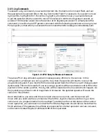
• Connect onboard control module to gateway using harness
• Supply power to the monitor by connecting the red and black leads from the 6 pin connector to
an appropriate power source. Install a 20 Amp fuse into the positive power lead for a 12V system
(10 Amp for 24V system) to protect the monitor electrical components.
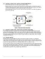
• Connect gateway to remote control unit. Figure 2-2 below provides an overview of the gateway
enclosure connections
Figure 2-2. Gateway Enclosure Connections
2-7 INSTALLATION STEP 4: CONFIGURE SYSTEM IF REQUIRED
This chapter provides instructions on how to initialize an installed HydroBlast cannon and
program all configurable options in the menu system to make the system ready for Normal
Operation. The HydroBlast cannon is typically pre-calibrated from the factory, and will default
the user programmable limits to the maximum safe operation of the cannon, only limited by
mechanical limitations.
2-7.1 TRAVEL LIMITS
Setting limits for the HydroBlast system’s horizontal and vertical rotation is a necessary
step for the HydroBlast systems. The limits serve as a starting point for all other motion and
commands. If not properly set, the system may not operate correctly. Travel limits can be used
to aid in avoiding objects that may interfere with the motions of the monitor.
It is important to note that travel range cannot be increased further than that range which was
set as system default during system configuration. If a larger travel range is desired, this must
be changed by reconfiguring the system via the plant/remote control unit. See Operational
and Programming Section for programming instructions.
Содержание HydroBlast 7100MG EXM2
Страница 28: ...5 2 5 5 NOTES...
Страница 29: ...5 3...
Страница 30: ...5 4...
Страница 31: ...5 5...


