Radio
Adapter
Pag. 7/12
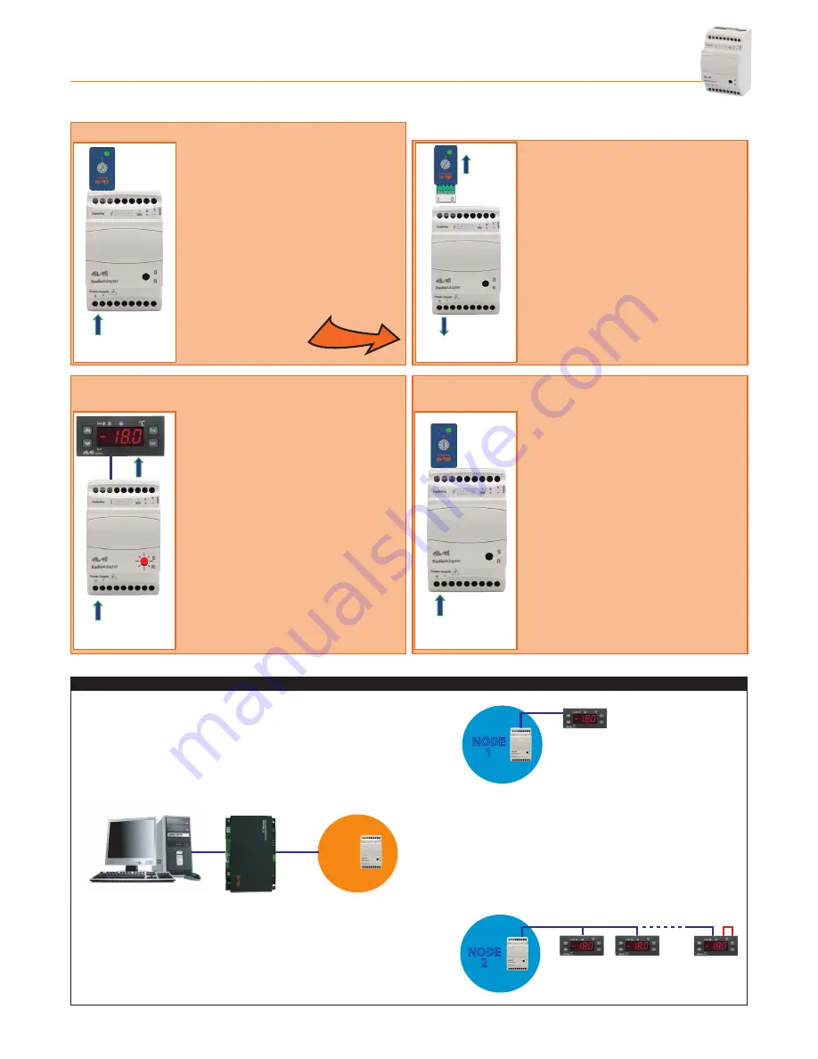
2.2 - HOw TO INSTALL A NODE
2.2.1 - INITIALIzING A NODE
Power
Supply
Power
Supply
Power
Supply
Power
Supply
Power
Supply
TTL +
RS485
- Connect the
Radio
Adapter to the power
supply.
- Set the switch on the
Radio
Key to
position
1
.
- Connect the
Radio
Adapter to the
Radio
Key and wait for the GREEN LED (N)
(on the
Radio
Key) to light up (YELLOW
LED(P) off). The
Radio
Adapter is now
configured as a NODE and information
on the type of network is sent to the
NODE.
Power
Supply
Power
Supply
Power
Supply
Power
Supply
Power
Supply
TTL +
RS485
- Disconnect the
Radio
Key when the
GREEN LED on the NODE starts to
blink.
- Disconnect the NODE from the
power supply.
2.2.2 - ADDRESS CONFIGURATION AND SEARCHING
FOR CONNECTED DEvICES
2.2.3 - SAvING SETTINGS
Power
Supply
Power
Supply
Power
Supply
Power
Supply
Power
Supply
TTL +
RS485
- Configure the Televis or Modbus address
of the devices to be connected to the
NODE.
- Connect the devices to the NODE via TTL
or RS-485.
- Switch on the devices connected and then
the NODE. The NODE will start to scan for
connected devices, which is indicated by
the fast blinking of the GREEN LED on the
NODE.
- The GREEN LED switches off and the RED
LED starts blinking on the NODE when the
scan is complete.
Power
Supply
Power
Supply
Power
Supply
Power
Supply
Power
Supply
TTL +
RS485
- Disconnect all devices from the NODE
without switching the NODE off.
- Set the switch on the
Radio
Key to
position
0
then connect the
Radio
Key
to the NODE.
- Wait for the GREEN LED (N) on the
Radio
Key to light up.
- Disconnect the
Radio
Key and connect
the devices properly.
IMPORTANT! Repeat the steps outlined above for each NODE to be installed in the network
NETWORK STRUCTURE
PAN-C
NODE
1
NODE
2
TTL/RS-485
RS-485
120 Ω
RS-485


