32
EN
Instruction Manual
EL 9000 HP Series
Date: 05-31-2011
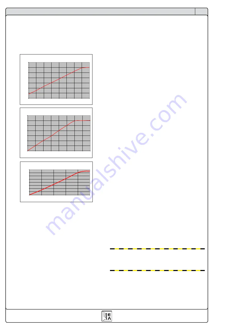
4.8 Relation of input voltage to input current
When working with applications that input only low voltages
to the load, it becomes necessary to know the minimum
input voltage that is required for the load to draw the full
input current. That minimum voltage is not zero and, de-
pending on the number of transistors inside, it varies from
model to model.
EL9080-600
I
e
zu U
e
/ I
in
to U
in
0
100
200
300
400
500
600
700
0,1
0,2
0,3
0,4
0,5
0,6
0,7
0,8
0,825
U
in
/V
I
in
/A
EL9160-300
I
e
zu U
e
/ I
in
to U
in
0
50
100
150
200
250
300
350
0
0,1
0,2
0,3
0,4
0,5
0,6
0,7
0,8
U
in
/V
I
in
/A
EL9400-150
I
e
zu U
e
/ I
in
to U
in
0
20
40
60
80
100
120
140
160
0.0
0.1
0.2
0.3
0.4
0.5
U
in
/V
I
in
/A
5. Installation
5.1 Visual check
After receipt, the unit has to be checked for signs of phy-
sical damage. If any damage can be found, the unit may
not be operated. Also contact your dealer immediately.
5.2 Mains connection
The mains connection is done with the included mains
cord.
The plug is a 10A mains plug after IEC 320. The mains
cord has a length of about 1.5m and a cross section of
3 x 0.75mm².
The unit is fused with a 5 x 20mm safety fuse (T2.5A),
which is accessible at the rear side
5.3 Terminal DC input
The load input is located at the rear side of the device.
The connection to any feeding source is done here by
the screws. Always take care for correct polarity! Only
DC voltages allowed!
The input is
not
fused. In order to prevent damages by the
feeding source always observe the nominal values of the
electronic load! If necessary, install an extra fuse between
load and source, especially when discharging batteries.
The cross section of the load cables depend on the cur-
rent input. We recommend to use:
at
150A
:
2 x 16mm² or at least 1 x 50mm²
at
300A
:
2 x 50mm² or at least 1 x 150mm²
at
600A
:
2 x 150mm²
per cable
(flexible wire).
The inputs “+” und “-“ are not grounded, so that
one
of
them may be grounded, if necessary.
Attention! When grounding one of the input poles
always check if one of the output poles of the source
(eg. power supply) is also grounded. This could result
in a short-circuit!
Attention! Notice the potential shift of the input poles
when using series connection! Grounding is hereby
only recommended at the pole with the lowest poten-
tial against ground.
5.4 Terminal System Bus
The terminal
System Bus
(rear side) is another interface
with important features. For pin assignment and detailed
description see section „6.12 Functions of the terminal
5.5 Using and connecting the remote sense
The remote sense feature is wired at terminal
System
Bus
. See section „6.12 Functions of the terminal System
Bus“ for more information.
In order to compensate voltage drops over the load cables
(max. 1.1V per line) between feeding source and con-
sumer, the load can measure the voltage at the source
via the remote sense input poles at the terminal
System
Bus
and regulates accordingly. The connection is done,
with correct polarity, at the rear side of the device at the
terminal
System Bus
, at pin 1 (+ Sense) and pin 4 (–
Sense). Recommended cross section: 0,2mm
2
– 2,5mm
2
flexible wire with cable end sleeves.
(+) Sense must only be connected to (+) output
and (–) Sense must only be connected to (–) output
of the feeding source. Else both device might get
damaged.
5.6 Interface card slot
The unit can be equipped with an optional interface card.
The slot to insert the card is located at the rear side.
Further information about the interface cards can be
found in section 9.
About the device
Содержание 33200246
Страница 2: ......
Страница 7: ...7 CN EL 9000 HP 系列 产品说明书 日期 05 31 2011 关于产品 3 外观 3 1 前视图 图 1 ...
Страница 8: ...8 CN EL 9000 HP 系列 产品说明书 日期 05 31 2011 关于产品 3 2 后视图 图 2 ...
Страница 24: ......
Страница 29: ...29 EN Instruction Manual EL 9000 HP Series Date 05 31 2011 About the device 3 Design 3 1 Front view Figure 1 ...
Страница 30: ...30 EN Instruction Manual EL 9000 HP Series Date 05 31 2011 About the device 3 2 Rear view Figure 2 ...


