33
• After making the connection, with the machine running check
that the power supply does not fluctuate by ±10% the rated
voltage.
Note:
In models arranged for operation with remote units, make
the
electrical connection to the condensing unit and solenoid valve
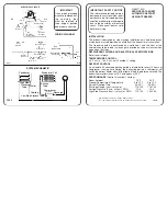
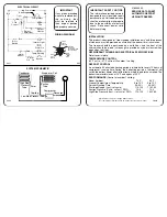
as shown in the wiring diagram attached to the appliance.
The connection must be made with cable of adequate
section.
If the power cable is damaged, it must be replaced by the
after-sales service or in any case by qualified personnel, in
order prevent any risk.
The manufacturer declines any liability for damage or injury
resulting from breach of the above rules or non-compliance
with the electrical safety regulations in force in the country
where the machine is used.
B.2.9 ELECTRICAL CONNECTION (ONLY FOR APPLIANC-
ES WITH CABLE WITHOUT PLUG)
Connection to the power supply must be carried out in compli-
ance with the regulations and provisions in force in the country
of use.
ATTENTION!
Work on the electrical systems must only be car-
ried out by a qualified electrician.
The information regarding the appliance power supply voltage
is given on the dataplate.
Before connecting, make sure:
`
`
the connection point has an efficient earth contact and the mains
voltage and frequency match that given on the data plate. In
case of doubts regarding the efficiency of the earth wire, have
the system checked by qualified personnel;
`
`
the system power supply is arranged and able to take the actual
current absorption and that it is correctly executed according
to the regulations in force in the country of use;
`
`
the appliance must be permanently connected to the power
supply, respecting the polarities:
- brown: phase
- yellow/green: earth
- blue: neutral;
`
`
a differential thermal-magnetic switch (or plug) suitable for the
absorption specified on the data plate, with contact gap enabling
complete disconnection in category III overvoltage conditions
and complying with the regulations in force, is installed between
the power cable and the electric line. For the correct sizing of
the switch or plug, refer to the absorbed current specified on
the appliance data plate
.
The chosen device must be lockable
in the open position in case of maintenance.
ATTENTION:
When using a plug, it must comply with the
national installation rules. The plug must also be:
`
`
accessible after the appliance has been positioned
in the place of installation;
`
`
in a position always visible to the operator perform-
ing the intervention during maintenance operations.
`
`
After making the connection, with the appliance running check
that the power supply does not fluctuate by ±10% the rated
voltage.
ATTENTION!
An H05VV-F power cable (designation 60227 IEC
53) is used for the permanent connection to the
power supply; when replacing it, use a type having
at least these characteristics.
ATTENTION!
When replacing the cable, the earth wire must be
kept longer than the live and neutral wires.
If the power cable is damaged, it must be replaced by the
service centre or in any case by qualified personnel, in
order prevent any risk.
The manufacturer declines any liability for damage or
injury resulting from breach of the above rules or non-
compliance with the electrical safety regulations in force
in the country where the machine is used.
ATTENTION: THE DOORS ARE NOT REVERSIBLE.
C.1 CONTROL PANEL
C.1.1 CONTROL PANEL
(see Fig.1)
C.1.2 DIGITAL THERMOSTAT DISPLAY
The digital thermostat has a 3-digit electronic display for showing
the temperature measured by the probe, and six
ICONS
(see
fig.1 and par. C.1.5).
C.1.3 BUTTONS
The digital thermostat has 4 buttons for control and programming
the instrument.
- Multifunction
“ON/OFF”
and
“UP”
button
for switching
the appliance on or off and increasing the values.
-
“DOWN”
and
“DEFROST”
button
for activating manual
defrost and decreasing the values.
-
“Prg/mute”
button
for silencing the alarm buzzer.
-
“SET”
button
for accessing the Set point.
C.1.4 SWITCHING ON AND TEMPERATURE ADJUSTMENT
When switched on, the instrument performs a Lamp Test, i.e.
for a few seconds the display and Icons flash, verifying its
correct functioning. If the instrument displays the compartment
temperature when switched on, the appliance is already on; if
“OFF” is displayed, press the
“ON/OFF”
button
for a few
seconds to activate the appliance
;
the display shows the message
“ON”
and then the compartment temperature.
To switch the appliance off, press the
“ON/OFF”
button
for a few seconds
;
the message
“OFF”
appears on the display.
To
SET
the compartment temperature, proceed as follows:
- Press the button
for a few seconds and the
SET POINT
value appears on the display.
- To change the
SET
value, press the
“UP”
increase value button
or the
“DOWN”
decrease value button
.
If no button is pressed for 60 seconds (
“TIME OUT”
), or by
pressing the
“SET”
button once, the digital thermostat memorises
the last set value and the normal display is restored.
The temperature range is set from a
minimum to a maximum, according to the following values:


