


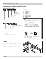


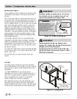
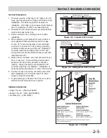
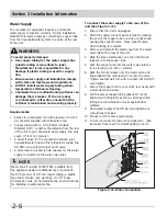


Section 2 Installation Information
2-7
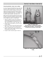
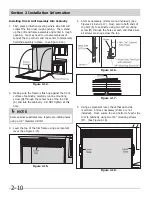
Figure 2-7b. Water Valves
The water valve on the left is the old style
threaded outlet connection. The water valve on
the right has the push-type outlet fitting.
Connecting the Water Valve to the Ice Maker
For models Serial Number WB92254219 and greater built
after June 1, 2009, the units will have a different water
valve than earlier production models. The new water
valves have a quick connect outlet fitting which takes a
standard .255 diameter plastic tube. The old style of
water valves required a flanged tube and a threaded nut
to make the water connection. (See Figure 2-7b)
Water Line Kit PN 297114101 will still be used to make
the water line connections between the new style water
valve and ice maker, however the flanged tube will have
to be modified as described in the steps below:
1. Using a box cutters or knife, cut the pointed end
from the water line just below the raised point. Be
sure to cut straight across the water line. Do not
leave open/cut end at an angle. (See Figure 2-7c)
2. Remove the cut end and plastic nut from the water
line and discard.
3. Measure 11/16” from the end of the water line and
place a mark on the line with a permenent marker.
4. Insert the modified water line into the push-type
fitting on the new valve, making sure that the water
line is pushed in up to the mark.
5. Inspect for leaks once water supply is turned on.
Figure 2-7. Water Connection
Figure 2-7c. Cut along dotted line to modify
tubing.
Содержание FPUH17D7KF All Freezer Professional Series
Страница 2: ......
Страница 20: ...Section 2 Installation Information 2 12 Figure 2 20 Figure 2 21 ...
Страница 21: ...Section 2 Installation Information 2 13 Figure 2 22 Figure 2 23 ...
Страница 24: ...Section 2 Installation Information 2 16 Notes ...
Страница 26: ...Section 3 Electronic Control 3 2 Notes ...
Страница 41: ...Section 4 Refrigeration 4 15 HFC 134a CFC 12 Pressure Temperature Chart ...
Страница 44: ...Section 4 Refrigeration 4 18 Notes ...
Страница 68: ...Section 6 Parts List 6 2 All Refrigerator Cabinet Exploded View And Parts List ...
Страница 70: ...Section 6 Parts List 6 4 All Refrigerator Sealed System Exploded View And Parts List ...
Страница 72: ...Section 6 Parts List 6 6 All Freezer Door Exploded View And Parts List ...
Страница 74: ...Section 6 Parts List 6 8 All Freezer Cabinet Exploded View And Parts List ...
Страница 76: ...Section 6 Parts List 6 10 All Freezer Sealed System Exploded View And Parts List ...
Страница 78: ...Section 6 Parts List 6 12 Notes ...
Страница 82: ...Section 7 Troubleshooting 7 4 Notes ...
Страница 83: ...Section 8 Wiring Diagram 8 1 All Refrigerator Wiring Diagram ...
Страница 84: ...8 2 Section 8 Wiring Diagram All Freezer Wiring Diagram ...


