Application manual
Interface for Load monitoring and control EK- CF2-TP
Revision 1.0.0 - Update: 04/07/2017
© EKINEX S.p.A.
– All rights reserved
MAEKCF2TP_IT
Pag. 16
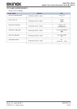
8.2. General settings
The parameters in this section define the overall behaviour of the device, including the setting that defines
which and how many channels are available.
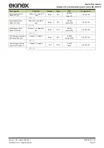
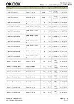
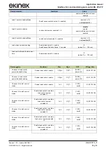
Nome parametro
Condizioni
Valori
Delay after bus voltage
recovery
00:00:03
hh:mm:ss
[campo 00:00:00 … 18:12:15]
Channel 1
enable CT input
enable from bus
disable
Power factor (cosf)
Channel 1 = enable CT input 1
Da 0,1 a 1
(
0,9)
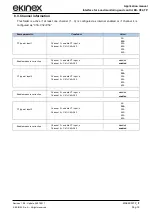
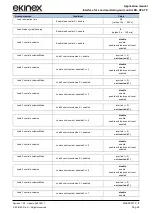
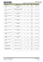
Channel 2
enable CT input
enable from bus
disable
Power factor (cosf)
Channel 2 = enable CT input 2
Da 0,1 a 1
(
0,9)
Channel 3
enable CT input
enable from bus
disable
Power factor (cosf)
Channel 3 = enable CT input 3
Da 0,1 a 1
(
0,9)
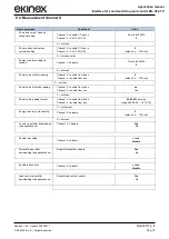
Power supply Voltage(V)
Channel 1 = enable CT input 1 o
Channel 2 = enable CT input 2 o
Channel 3 = enable CT input 3
Da 220 a 440 Vac
230
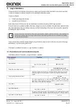
Channel 4
Ch1+Ch2+Ch3
enable from bus
disable
Power supply Voltage(V)
Channel 4 = Ch1+Ch2+Ch3
Da 220 a 440 Vac
400
Power factor (cosf)
Channel 4 = Ch1+Ch2+Ch3
Da 0,1 a 1
(
0,9)
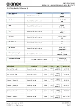
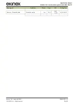
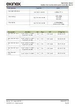
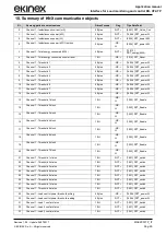
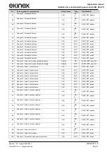
Nome oggetto
Condizioni
Dimens.
Flags
DPT
Nr. Ogg. Com.
Instantaneous current
Channel X (mA)
Channel X = enable CT
input
4 Byte
CR---
[9.021]
DPT_Value_Curr
0,51,102,153
X = 1..4


