Application manual
Interface for Load monitoring and control EK- CF2-TP
Revision 1.0.0 - Update: 04/07/2017
© EKINEX S.p.A.
– All rights reserved
MAEKCF2TP_IT
Pag. 10
6.3.3
TA configuration
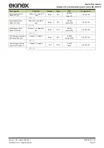
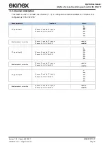
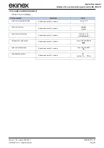
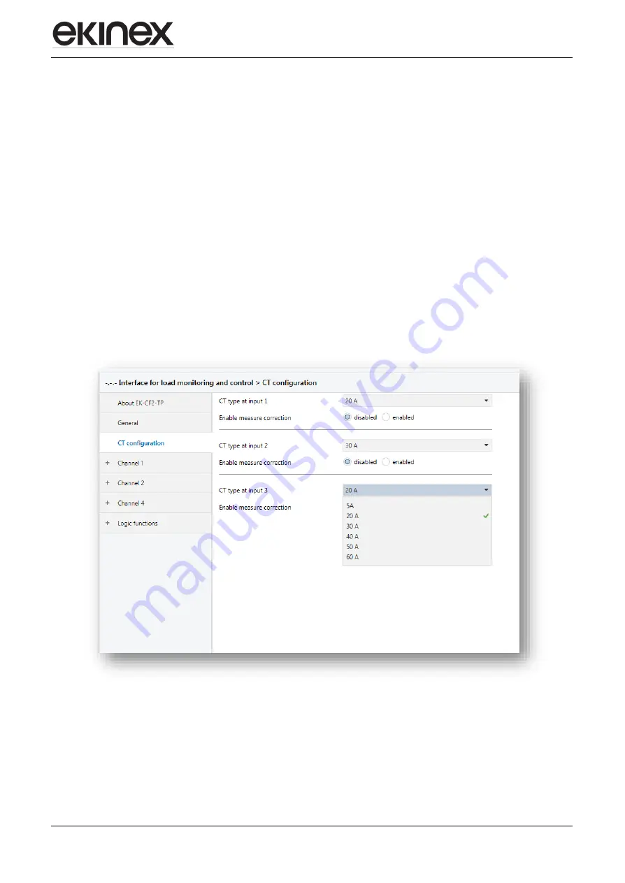
In this section, the TAs to be connected to channels 1-2-3 can be parametrized, by inserting the measurement
range characteristics (5, 20, 30, 40, 50 and 60 A).
Moreover, it is posYesble to perform a calibration for a more precise and linear measurement.
I
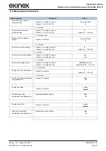
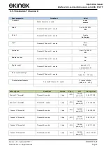
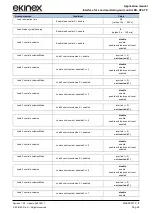
f the parameter “Enable measurement correction” is enabled, you can proceed to insert the requested values
in the windows called “current point x measured by input and channel”.
Pratically, you must proceed like this:
Through ETS > Diagnostics, verify the current measurement detected in a point with low absorption,
inserting the detected value in the window called “Current point 1 measured by input”.
Without changing load or conditions, with a current clamp, measure the current and insert the value in
the w
indow called “current point 1 measured by user”.
Increase the load, according to the maximum measurement of the TA, and repeat the two measurements
inserting them in the windows called respectively “Current point 2 measured by input” and “Current point
2
measured by user”.
This way, the device will perform an auto-calibration of the absorbed current linearization curve, in order to
obtain measurements that are more precise.


