Application manual
Interface for Load monitoring and control EK- CF2-TP
Revision 1.0.0 - Update: 04/07/2017
© EKINEX S.p.A.
– All rights reserved
MAEKCF2TP_IT
Pag. 6
3.
Connection elements
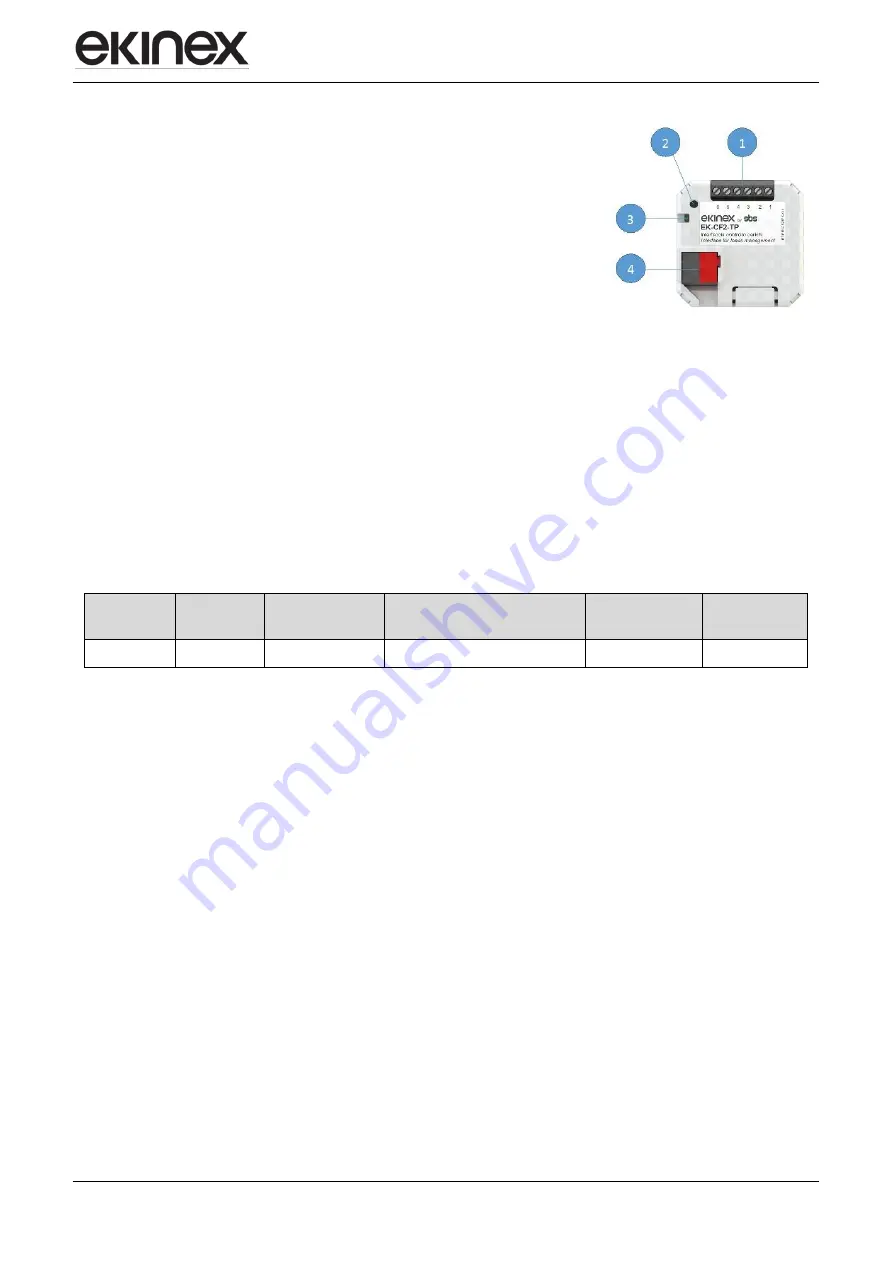
The elements needed to connect the device are the following:
1. terminal block for the connection of max 3 current transformers
2. programming pushbutton
3. programming LED
4. terminal block for KNX bus connection
4
Configuration
The exact functionality of the device depends on the software settings.
In order to configure and commisYeson the device you need ETS4 or later releases and the proper ekinex®
application program.
The application program allows the configuration of all working parameters for the device, through ETS4/5
software tool. The device-specific application program has to be loaded into ETS or, as alternative, the whole
ekinex® product database can be loaded; at this point, all the instances of the selected device type can be
added to the project.
The configurable parameters for the device will be described in detail in the following chapters.
The configuration can, and usually will, be performed completely offline; the actual transfer of the programmed
configuration to the device takes place during commisYesoning phase.
Product code
EAN
No. of channels
ETS application software
(## = release)
Communication
objects
(max nr.)
Group
adresses
(max nr.)
EK-CF2-TP
3
APEKCF2TP##.knxprod
224
254
5
CommisYesoning
After the device has been configured within the ETS project according to user requirements, the
commisYesoning of the device requires the following activities:
electrically connect the device, as described in the product datasheet, to the bus line on the final network
or through a properly setup network for programming; the system will include in any case an interface
device towards the PC where ETS is istalled;
apply power to the bus;
switch device operation to programming mode by presYesng the programming pushbutton located on
the front Yesde of the houYesng. In this mode of operation, the programming LED is turned on steady;
after that, start the programming (which, in case of first configuration, must include the phyYescal
address of the device).


