


42
6.1
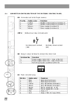
CONNECTOR CONFIGURATION OF THE INTEGRA CONTROL PANEL
X3
: Connector set to the finger scanner
Pin No.
Cable color
Function
1
Yellow
RS485 communication (terminal 2)
2
Green
RS485 communication (terminal 1)
3
Brown
Power supply (terminal 3)
4
White
Power supply (terminal 4)
JMP2
:
Defines how relay 2 should work
Normally open contact
Normally closed contact
(NO)
(NC)
X6
: Relay 1 screw terminal to connect the motor lock
Terminal No.
Function
1
Power supply motor lock + (equ. white X1)
2
Power supply motor lock - (equ. brown X1)
3
Switching impulse (switched white X1)
X1
: Main connector plug
Pin No.
Cable color
Function
1
Blue
Gate input terminal 1
2
Grey
Gate input terminal 2
3
Yellow
ekey TOCAhome terminal 2
4
Green
ekey TOCAhome terminal 1
5
Brown
Power supply DC- or AC
6
White
Power supply DC+ or AC
7
Pink
Relay 2 C
8
Red
Relay 2 NO / NC (see JMP1)
3
2
1
1
3
4
2
1
2
3
1
5
4
8
JMP2
Содержание TOCAhome 2 integra
Страница 11: ...11 ...
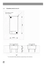
Страница 16: ...16 6 2 ABMESSUNGEN DER STEUEREINHEIT INTEGRA ...
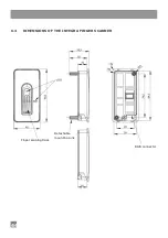
Страница 17: ...17 6 3 ABMESSUNGEN DES FINGERSCANNER INTEGRA ...
Страница 19: ...19 7 2 AUSFRÄSUNG FINGERSCANNER empfohlene Fräsmasse können je nach Werkstoff variieren ...
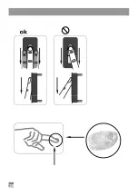
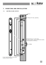
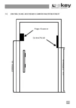
Страница 22: ...22 1550m m c a 1 300m m Fingerscanner Steuereinheit 7 5 MONTAGEHÖHE FÜR STEUEREINHEIT UND FINGERSCANNER ...
Страница 28: ...28 ...
Страница 38: ...38 ...
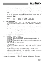
Страница 43: ...43 6 2 DIMENSIONS OF THE INTEGRA CONTROL PANEL Shield width ...
Страница 44: ...44 6 3 DIMENSIONS OF THE INTEGRA FINGER SCANNER Finger swiping track Detachable mounting pins RJ45 connector ...
Страница 54: ...54 ...


