

E D R O
D
y n a
W
a s h
®
T
h r e e
P
o c k e T
W
a s h e r
- e
x T r a c T o r s
24
The design of the DynaWash
®
machine emphasizes performance reliability and long service
life. All fabricated wetted parts are stainless steel, and wetted component parts are either brass
or bronze.
The cylinder is driven by one of two methods DW_PT & DW_PTSM models have a set of belts
going through an extract motor, a clutch and brake assembly, and wash motor. The DW & DW_
SM models have an inverter with a single motor drive. The flywheel is supported via the shaft
by flange-mounted spherical roller bearings bolted to the front and back plates of the machine.
The cylinder is constructed of formed baffles and ribs that lift the laundry from the bath solution
when it rotates at slow speed then allowing the laundry to tumble back into the bath. This
mechanical action accomplishes the washing function. The cylinder is perforated, allowing the
water to drain from within during the wash and extract steps. The shaft, bearing and seal
assembly includes a full length stainless steel shaft supported on both ends by flanged
bearings mounted in a precision machined stainless steel bearing adapter housing. The cavity
in the housing allows for the installation of two, single lip seals, which maintain contact with the
bearing on the shaft and separate the wash water from entering the bearing and the bearing
grease from entering the wash water.
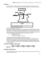
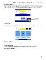
The electrical controls for DynaWash
®
machines are housed in a separate enclosure located on
the side of the machine. Turning the key on panel cover and opening the panel door provides
access to the electrical components. These include the control, PLC and other control
components.
Chemicals may be added to the machine in a variety of methods. The standard system sup-
plied with DynaWash
®
consists of a manual hopper either located on the right side of the ma-
chine (DW and DW_SM models) or on the soiled side plate (DW and DW_SM models), and 10
ports for liquid supplies located on the right side of the machine. A terminal strip located in the
control panel provides connection points for the external signals. An optional flushing supply
system consists of a stainless steel supply hopper and flushing solenoid valves connected to
the hot water valve. The dispenser has five supply compartments. The compartments hold
plastic supply cups that may be used for either liquid or dry supplies. A nozzle flushes the sup-
plies from the cups with water for a predetermined programmed time. Dry supplies are placed
in the supply dispenser compartment cups at the start of each cycle. Ports for liquid chemicals
are also provided with the supply hopper.
Standard production of DynaWash
®
use one single drain valve. The drain valve is normally
open, which means that it closes only when power is applied, thus allowing the machine to drain
in the event of a power failure.
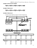
The wash load should be divided into three equal parts, not more than 10% difference in
weights and between 95 and 105% of total rated capacity. Best results are obtained when the
load is kept within the machine’s full rated capacity. Do not mix loads. Use the same type of
washable material for each load (towels only, sheets only, etc.). If the fabric to be washed is
quite dense and heavily soiled overloading can result in an inferior wash. The operator may
need to experiment to determine load size based on fabric content, soil content, and level of
cleanliness required. When loading is complete, ensure that all fabric is inside the cylinder.
Then close and lock the door.
DESIGN AND CONSTRUCTION