pag.6
LB1292
MULTIFLAM 500.1 PR - 600.1 PR
techniques for energy saving
tecniche per il risparmio energetico
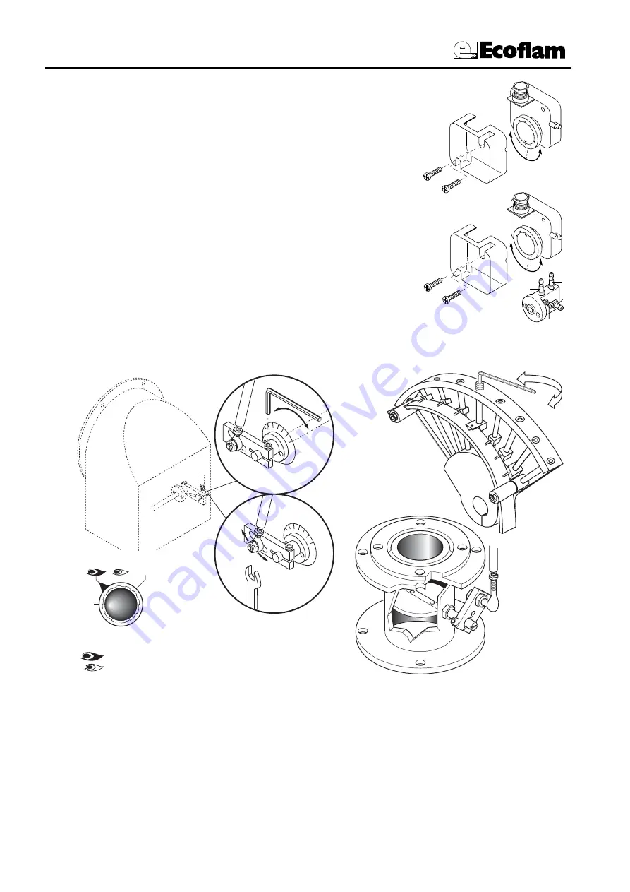
ADJUSTMENT OF GAS MINIMUM PRESSURE SWITCH
Unscrew off and remove cover M. - Set regulator N to a value equal to 60% of gas nominal feed
pressure (i.e. for nat. gas nom. pressure = 20 mbar, set regulator to a value of 12 mbar; for L.P.G.
nom. pressure of G30/G31- 30/37 mbar, set regulator to a value of 18 mbar).Screw up cover M
ADJUSTMENT OF THE AIR PRESSURE SWITCH
Unscrew screws A and B and remove cover C.- Set the pressure switch to the minimum by
turning regulator D to position 1.
- Start the burner and keep in low flame running, while checking that combustion is cor-
rect. Through a small cardboard, progressively obstruct the air intake until to obtain a
CO2 increase of 0,5÷0,8% or else, if a pressure gauge is available, connected to pressure
port E, until reaching a pressure drop of 1 mbar (10 mm of W.G.). - Slowly increase the
adjustment value of the air pressure switch until to have the burner lockout. Remove the
obstruction from the air intake, screw on the cover C and start the burner by pressing the
control box rearm button.
Note: The pressure measured at pressure port E must be within the limits of the pressu-
re switch working range. If not, loose the locking nut of screw F and gradually turn the
same: clockwise to reduce the pressure; counterclockwise to increase. At the end tighten the
locking nut.
2,5
5
10
15
50
2
5
35
30
40
45
20
0,4
0,6
0,9
3,0
1
,5
2,1
1,8
2,4
2,7
1,2
I
L
M
N
A
B
C
D
E
F
G
H
Gas pressure
switch
Air pressure
switch
+
- -
Part. 1
Part. 2
Part. 3
-
+
-
COMMUTATORE
0
AUTO
0 = bloccaggio degli apparati per il
funzionamento in una posizione intermadia
= funzionamento alla massima potenza
= funzionamento alla minima potenza
AUTO = funzionamento automatico
AIR ADJUSTMENT
operating elements locked in an intermediate
position
operation on maximum capacity
operation on minimum capacity
automatic operation
SELECTOR
ADJUSTING THE MINIMUM CAPACITY OF THE BURNER – AIR and GAS
Position the selector placed on the control panel on position 2 and proceed as follows:
Adjust the minimum gas flow rate using a suitable wrench, turn the butterfly valve until you reach the correct gas
flow, as established by analyzing the combustion process.
ADJUSTING THE MAXIMUM CAPACITY OF THE GAS
Position the selector, situated on the control panel, on position 1 and proceed as follows:
Adjusting the maximum gas flow rate (see figure on solenoid valve adjustments) or adjust the gas pressure in the
governor.


