


pag.14
LB1292
MULTIFLAM 500.1 PR - 600.1 PR
techniques for energy saving
MAINTENANCE
YEARLY CHECKS
The burner’s periodical check (firing head, electrodes etc.) must be carried out by authorised personnel one or two times per
year, depending on the utilisation. Before going on with the maintenance controls of the burner, it should be advisable to check
its general conditions, according to the following steps:
Unplug the burner; close the fuel cock; shut down the gas supply; remove burner’s cover and clean the fan and air intake; clean
the firing head and check the electrode’s position; reassemble all the parts; check the connection’s sealing; check the chimney;
start the burner and check the combustion flue (CO2 = 9.5 ÷ 9.8; O = lower than 75 ppm).
BEFORE EVERY INTERVENTION CHECK:
The electric system is duly powered and the burner is plugged in.
The gas pressure must be the suitable one and the gas cock open.
The control devices must be properly connected.
When all the above conditions are met, start the burner by pressing the lockout enable pushbutton.
Check the burner’s cycle.
THE BURNER DOES NOT START:
Check the ON/OFF switch, the thermostats, the motor and the gas pressure.
The master switch is in position “0”. Fuses are blown out.
The control box is faulty.
THE BURNER RUNS THE PREPURGING AND SWITCHES TO LOCKOUT AT THE END OF CYCLE:
Check the fan and the air pressure.
Check the air pressure switch.
Control box faulty. Ignition transformer faulty.
Check the ignition cable. Electrodes are dirty or in wrong position.
Nozzles are clogged or worn. Filters are clogged. Light-oil pressure is too low.
Combustion air’s flow rate too high related to nozzle output.
THE BURNER RUNS THE PREPURGING BUT DOES NOT IGNITE:
Check the position of the electrodes; check the ignition cable;
Check the ignition transformer;
Check the control box.
THE BURNERS IGNITES BUT SWITCHES TO LOCKOUT AFTER THE SAFETY TIME:
Check phase and neutral for a correct connection.
Check gas solenoid valve.
Check the position of ionisation probe and its connection.
Check the control box.
Check nozzles (clogged or worn).
The photoresistor does not detect the flame.
The filters are clogged. Light-oil pressure too low.
Combustion air’s flow rate too high related to nozzle output.
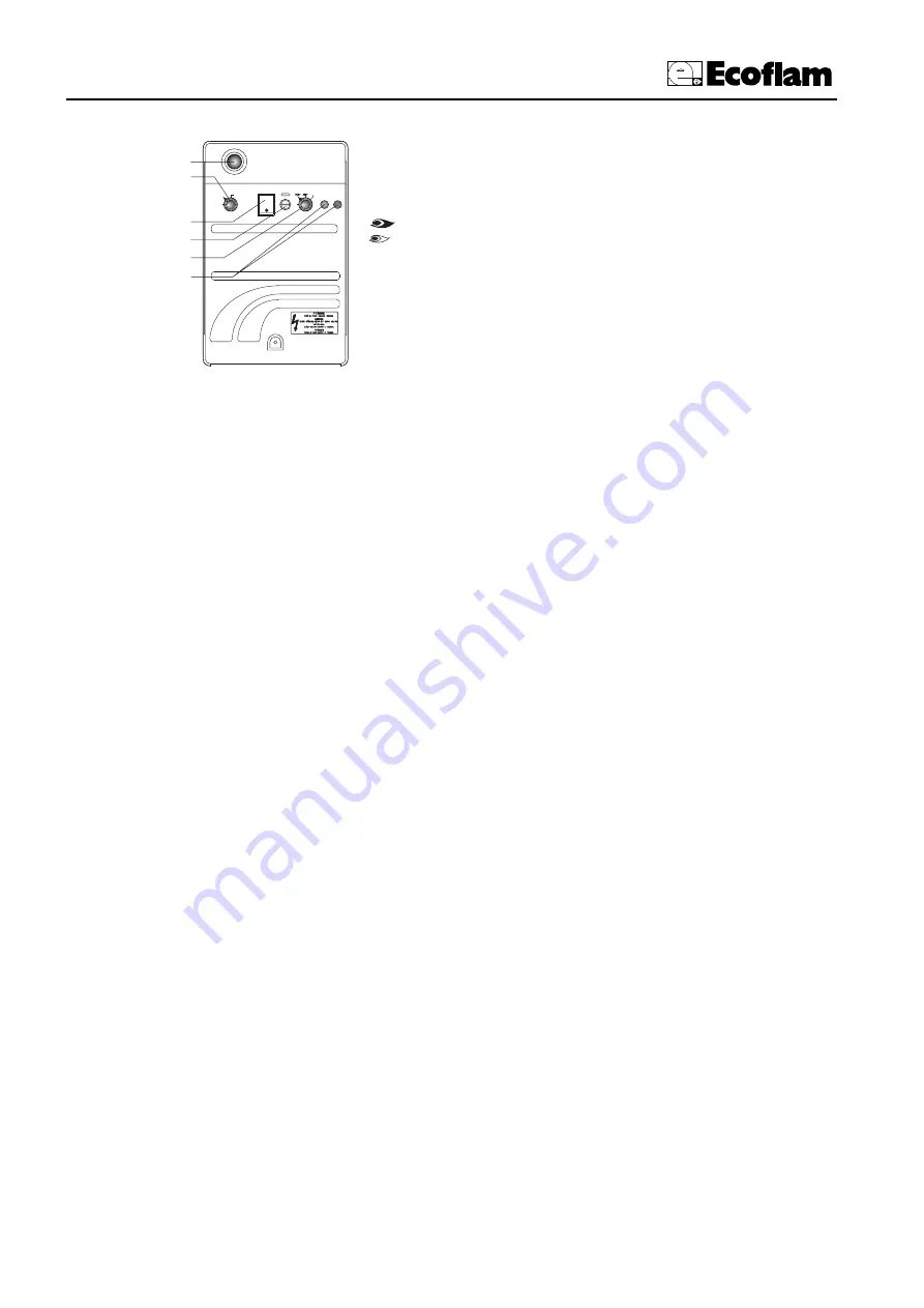
A - main switch I/0
B - operating lamps (orange=light-oil; green= gas)
C - Selector switch:
0 =
Loking of devoices for operating at intermediate outputs
=
Operation at max. output
=
Operation at min. output
AUTO
=
Automatic operation
D - ON/OFF switch
E - Fuse holder
F - Selector:
0 = STOP
1 = Light-oil operation
2 = Gas operation
3
funzionamento automatico
A
B
C
D
E
F
0
1
2
0 - STOP
1 - GASOLIO
2 - GAS
0
AUTO
DESCRIPTION OF CONTROL PANEL
Heavy


