ETS 73
0548-990-51---60g_2019.10.indd
E
5 Nm
C
B
A
90°
C
B
320
353...594
20
19
19
29
22
4
25 Nm
9 Nm
D
0548-990/52g
Page 24 of 98
Mounting and operating instructions
Drive mechanism standard
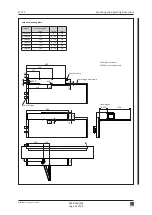
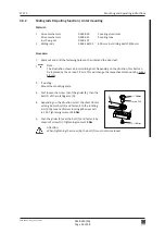
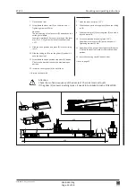
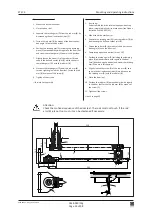
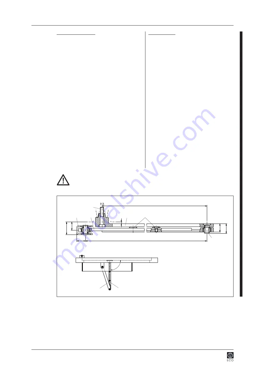
5. Close the door leaf.
6
. Separate the rotating arm (C) from the rod arm (B) by
loosen the screw (E).
7. Fasten the rod arm (B) by means of the door connec
-
tion angle (A) onto the door leaf.
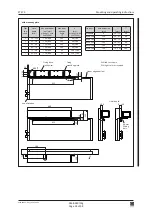
8. Position the rotating arm (C) perpendicularly with
regard to the door leaf and screw it down in this posi
-
tion
Tightening moment 25 Nm
.
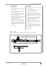
9. Slightly loosen the screws (D) and the rotating arm (C),
fasten them by means of the screw (E) to the rod
arm (B)
Tightening moment 5 Nm.
Attention:
Adjust the rods to the required length. Choose the
largest possible distance between both screws (D).
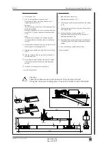
10. Prestress the rotating arm (C) until the rod arm (B)
forms a right angle with the door leaf. Fasten the rod
arm (B) by means of the screws (D)
Tightening
moment 9 Nm.
forward to chapter 4.6
Attention:
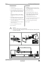
Check the motional sequence of the door leaf: The rods must not touch!
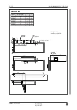
Inverse application
5
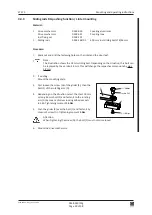
. Separate the rotating arm (C) from the rod arm (B) by
loosen the screw (E).
6. Fasten the rod arm (B) by means of the door connec
-
tion angle (A) onto the door leaf.
7. Completely open the door leaf (max. 110°).
8. Position the rotating arm (C) perpendicularly with
regard to the door lintel (direction open position) and
screw it down in this position
Tightening moment
25 Nm
.
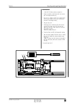
9. Slightly loosen the screws (D) and the rotating arm (C),
fasten them by means of the screw (E) to the rod
arm (B)
Tightening moment 5 Nm.
Attention:
Adjust the rods to the required length. Choose the
largest possible distance between both screws (D).
10. Close the door leaf.
11. Prestress the rotating arm (C) until the rod arm (B)
forms a right angle with the door leaf. Fasten the rod
arm (B) by means of the screws (D)
Tightening
moment 9 Nm.
forward to page 25


