ETS 73
0548-990-51---60g_2019.10.indd
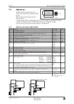
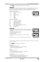
Default
OFF
95°
Ao depen
-
ding (95°)
0°
OFF
20 s
INACTI
CL-SPR
OFF
CLOSED
OPEN
ERROR
GONG
OPENING
CLOSING
PSAUTO
LOCKED
IMPULS
OFF
UNLOCK
LOCK
UNLOCK
0
OFF
OFF
NO ACT
OFF
APuGo
ASES
ASER
SeOpCo
SeOpTi
SESClo
EMY-IN
OExStp
RC 0.1
RC 0.2
RC 0.3
RC 0.4
RC 1.1
RC 1.2
RC 1.3
RC 1.4
Unlock
EL-Fb
LockAU
LockEX
LockMA
LcdDir
MovCon
OExMAN
PSKIZe
SCBloc
OFF, 2...10°
45°...Ao
0...60°
OFF
ON
PERMAN
1...60 s
ACTIVE
INACTI
CL-SPR (spring)
STOP
OPEN
CL-MOT (motor)
OFF
OEI
OEO
KEY
RADIO
CLOSED
OPENING
OPEN
CLOSING
ERROR
PSAUTO
PSNIGHT
PSEXIT
PSOPEN
PSMANU
GONG
LOCKED
SIX30S
EMY_AL
IMPULS
PERMAN
OFF
N.O.
N.C.
UNLOCK
LOCK
UNLOCK
LOCK
UNLOCK
LOCK
0...1
OFF
ON-FLT
ON-PRM
OFF
ON
NO ACT
PSOPEN
PSHAND
PSAUTO
PSEXIT
PSNIGT
OFF
TOGGLE
TIME
0548-990/52g
Page 68 of 98
Mounting and operating instructions
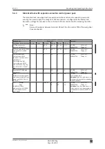
7.4.2
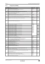
Configuration (CONFIG)
Parameter Description
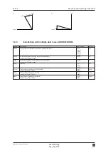
Triggering angle Push&Go (angle push&go)
1) Suppression point Safety Element stop (angle safety element stop).
If Ao is changed, ASES is auomatically set to Ao.
2) Suppression range of the safety element reversing (angle safety element reversing)
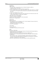
Persistent opening (saferty element open continue)
After a Safety Element Stop during the opening procedure, the door shall continue its opening move (instead
of closing), as soon as SES is activated.
Waiting time till the drive mechanism closes even if SeOpCo = ON (saferty element opening time), in the
event that a fixed object blocks the door (only visible if SeOpCo = ON)
Safety element Stop activated/deactivated during the closing motion (safety element stop closing)
Configuration of the Emergency terminal (break contact) (emergency input)
Step-by-step control function (opening element step)
Parametrizable relay output 1 on optional PCB 1 (relay contact)
(only visible if relay PCB 0 is plugged in)
Parametrizable relay output 2 on optional PCB 1 (relay contact)
(only visible if relay PCB 0 is plugged in)
Parametrizable relay output 3 on optional PCB 1 (relay contact)
(only visible if relay PCB 0 is plugged in)
Parametrizable relay output 4 on optional PCB 1 (relay contact)
(only visible if relay PCB 0 is plugged in)
Parametrizable relay output 1 on optional PCB 2 (relay contact)
(only visible if relay PCB 1 is plugged in)
Parametrizable relay output 2 on optional PCB 2 (relay contact)
(only visible if relay PCB 1 is plugged in)
Parametrizable relay output 3 on optional PCB 2 (relay contact)
(only visible if relay PCB 1 is plugged in)
Parametrizable relay output 4 on optional PCB 2 (relay contact)
(only visible if relay PCB 1 is plugged in)
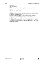
Impulse/Permanent unlocking (impulse unlock)
Return signal of the electric lock (electric lock feed back)
N.O.
Contact open if in the unlocked state (-), .closed if iin the locked state (+)
N.C.
Contact open in the locked state (+), closed in the unlocked state (-)
(+) and (-) indicate the status in the diagnostic menu.
Operating mode AUTOMATIC locked (locked automat)
(only visible if Unlock = Perman)
Operating mode EXIT locked (locked exit)
(only visible if Unlock = Perman)
Operating mode MANUAL locked (locked manual)
(only visible if Unlock = Perman)
Orientation of the display (LCD direction)
Endurance test Open/Close (moving continuous)
Acceptance of opening commands after a manual door opening (only if APuGo = OFF)
(opening element inside/outside manual)
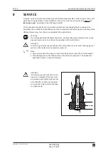
Zero position of the program setting (operating mode); fixed program position that can only be changed by
means of the terminals on the control unit (program selector key in the side cover inactive).
Use for external program switch (only four terminals) or for controlling the program positions via the termi
-
nals on the control unit.
(program selection terminal zero)
Lock the program selector key in the side cover (side cover block)
Toggle = Lock/unlock (press active program key during at least 5 seconds).
Time = Lock (automatically after 5 minutes without any activation of the program keys), unlocking (press
active program key during at least 5 seconds).
Setting range


