ETS 73
0548-990-51---60g_2019.10.indd
B
D
C
E
A
C
E
B
B
A
C
C
A
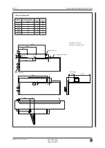
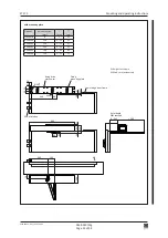
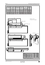
30
1,5
1,5
650
22
400
4
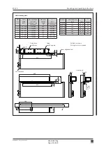
≈ 7,5°
D
E
25 Nm
0548-990/52g
Page 33 of 98
Mounting and operating instructions
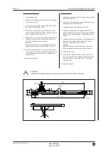
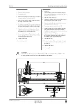
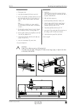
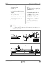
Attention:
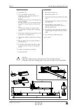
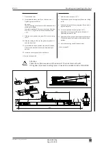
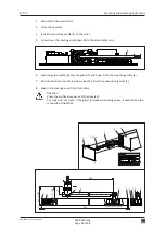
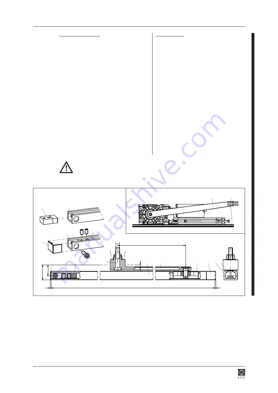
Check the motional sequence of the door leaf: The rods must not touch!
If the glider (E) makes screeching noises, it needs to be lubricated wih a little WD40.
Drive mechanism standard
7. Close the door leaf
.
8. Screw down the lever arm (D) on the drive unit
Tightening moment 25 Nm.
Attention:
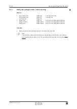
The pre-stressing of the lever arm (D) depends on the
existing lintel depth.
Example: Lintel depth 0 mm, pre-stressing of the lever
arm (D) ≈ 7,5° (1 grid increment of the output shaft
= 15°).
9. Slide the open position stop piece (B) into the sliding
rail (C).
10. Slide the sliding rail (C) over the glider (E) and bolt it
onto the door leaf.
11. Screw down the open position stop piece (B) approx.
5° before the door leaf reaches the maximum open
position.
12. Insert the covering caps (A) on both sides.
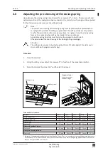
forward to chapter 4.6
Inverse application
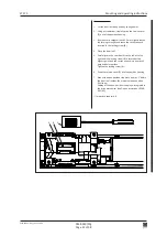
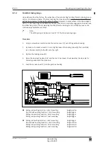
7. Open the door leaf (max. 115°).
8. Slide the open position stop piece (B) into the sliding
rail (C).
9. Slide the sliding rail (C) over the glider (E) and bolt it
into the door leaf.
10. At the complete door opening (max. 115°):
Screw down the lever arm (D) on the drive unit
Tightening moment 25 Nm.
11. Screw down the open position stop piece (B) approx.
5° before the door leaf reaches the maximum open
position.
12. Insert the covering caps (A) on both sides.
back to page 25


