Eclipse EC-P8 Скачать руководство пользователя страница 33

P0031-LI-02.01 

33 

7. On-board Communicator 

This section covers programming of the on-board communicator. 

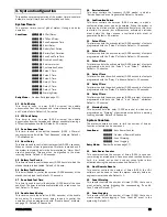
ARC 1-4: Telephone Number 

This set of options allows the telephone number to be 
programmed for each ARC. 

Locations:


7001

 to 

7004


ARC 1 to 4: Telephone Number. 

Entry Mode:

  String Edit - Number Mode (see page 17). 

Whilst programming telephone numbers, addition characters can 
be inserted to perform the following: 

B1

: Insert a “P” for a 1 second pause. 

B2

: Insert a “F” to force blind dialling (no dial-tone detection). 

ARC 1-4: Account Number 

This set of options allows the account number to be programmed 
for each ARC. 

Locations:


7011

 to 

7014


ARC 1 to 4: Account Number. 

Entry Mode:

  String Edit - Number Mode (see page 17). 

ARC 1-4: Protocol 

This set of options allows the protocol type to be programmed for 
each ARC. 

Locations:


7021

 to 

7024


ARC 1 to 4: Protocol. 

Entry Mode:

  Selection List (see page 15). 

0 Disabled 

The selected ARC is disabled.  

1 Contact 

ID 

The selected ARC is configured for Contact ID protocol. When 
triggered, the on-board communicator will dial the telephone 
number and attempt to communicate with the alarm receiver 
using Contact ID protocol.  

2 Fast 

Format 

The selected ARC is configured for Fast Format protocol. When 
triggered, the on-board communicator will dial the telephone 
number and attempt to communicate with the alarm receiver 
using standard Fast Format protocol. The control panel supports 
16 Fast Format channels, see “Fast Format” on page 34. 

3 Reserved 

The option is reserved and should not be selected. 

4 SMS 

Text 

The selected ARC is configured for SMS protocol. When triggered,   
the on-board communicator will dial the SMS Centre and send a 
SMS text message to the telephone number programmed in the 
ARC. See page 31 for programming the SMS Centre number. 

ARC 1-4: Protocol Options 

This set of options allows the protocol options to be programmed 
for each ARC. 

Locations:


7031

 to 

7034


ARC 1 to 4: Protocol Options. 

Entry Mode:

  Bit Toggle Selection (see page 16). 

Switch to Next ARC on failed Attempt 

On:  The on-board communicator switches to the next ARC in the 

sequence, if the current ARC attempt fails.  

Off:  The on-board communicator continues dialling the selected 

ARC until all its attempts have been used. 

Use PSTN Pre-Dial 

On: The on-board communicator dials the “PSTN Pre-Dial 

Number” before dialling the ARC telephone number. This is 
normally required when using an internal telephone system. 
See “PSTN Pre-Dial Number” on page 34.  

Off:  The on-board communicator only dials the ARC telephone 

number. 

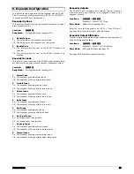
ARC 1-4: Call Sequence/Attempts 

This set of options allows the call sequence to be programmed for 
each ARC. 

Locations:


7041

 to 

7044


ARC 1 to 4: Call Sequence/Attempts. 

Entry Mode:

  String Edit - Number Mode (see page 17). 

The call sequence is entered as a string of digits; each number 
indicates the calling method: 

1= PSTN (On-board Communicator) 

2 = GSM Module 

3 = IP Module  

The call attempts are controlled by how many digits are entered. 
Here are some typical examples: 

“111” = Attempt to call the selected ARC three times using the 
PSTN. 

“1212” = Attempt to call the selected ARC four times alternating 
between PSTN and GSM. 

“123” = Attempt to call the selected ARC three times using PSTN, 
then GSM and finally IP. 

“31” = Attempt to call the selected ARC twice, first using IP then 
PSTN. 

ARC 1-4: Reported Event Groups 

This set of options allows you to control which group of events 
that are reported for each ARC. 

Locations:


7051

 to 

7054


ARC 1 to 4: Reported Event Groups. 

Entry Mode:

  Bit Toggle Selection (see page 16). 

1 Alarms 

On:  The selected ARC reports events that are assigned in the 

alarm group.  

Off:  The selected ARC does not report alarm events. 

2 Tampers 

On:  The selected ARC reports events that are assigned in the 

tamper group.  

Off:  The selected ARC does not report tamper events. 

3 Faults 

On:  The selected ARC reports events that are assigned in the 

fault group.  

Off:  The selected ARC does not report fault events. 

4 Open/Close 

On:  The selected ARC reports events that are assigned in the 

open/close group.  

Off:  The selected ARC does not report open/close events. 

5 Test/Misc. 

On:  The selected ARC reports events that are assigned in the 

test/misc. group.  

Off:  The selected ARC does not report test/misc. events. 

Содержание EC-P8

Страница 1: ...EC P8 8 18 Zone Intruder Alarm System Installation Manual...

Страница 2: ...ak Test 20 Zone Text 20 Zone Link 20 2 Arming Control 21 Arming Timers 21 Arming Modes 21 Arm Options 1 21 Arm Options 2 22 Arm Keyswitch Control 22 Auto Arm Disarm 22 3 System Configuration 23 System...

Страница 3: ...Outputs 12 38 Do Test Call 13 38 View Event Log 21 38 Print Event Log 22 38 Call UDL 23 38 Chime on off 24 38 Change Code 81 38 Program Mode 91 38 View Zone Status 92 38 Exit Menu 99 38 Log Events 39...

Страница 4: ...4 P0031 LI 02 01 1 System Overview System Configuration...

Страница 5: ...m fault messages A set of dedicated system status LEDs for AC Trouble and Alert are also provided Other features include f 4 wire connection using standard alarm cable f Internal sounder f Backlit key...

Страница 6: ...he control panel on a flat plumb wall using at least three appropriate screws The rear casing has been designed with a central key hole slot so that mounting is possible without removing the Printed C...

Страница 7: ...y Module 4 Mains Supply Cable Entry The mains supply cable must be routed into the control panel housing via this cable entry 5 ECM Module An optional Eclipse Communication Module ECM can be clipped i...

Страница 8: ...1 and 2 default to bell and strobe operation but can be programmed for other functions if required see page 28 for programming details Each output can also be programmed for supervision monitoring see...

Страница 9: ...her and wired into the terminal at the control panel only The maximum recommended distance for devices when using standard 7 0 2 alarm cable is f 250m for each branch when using the star parallel conf...

Страница 10: ...he EC P8 provides 8 zones for connecting detection devices such as movement sensors and magnetic door contacts Each zone is fully programmable to allow for maximum flexibility see page 18 for Zone Pro...

Страница 11: ...etector 2 Detectors Alarm Tamper E O L Alarm Tamper Alarm Tamper E O L 4K7 2K2 4K7 4K7 2K2 Triple EOL This wiring configuration should be used when connecting detection devices that support triple EOL...

Страница 12: ...he external sounder strobe unit Control Panel 12V TR 0V 1 2 External Sounder Tamper 0V 12V Suppy Bell ve Strobe ve Panel Outputs 1 4 The control panel has four programmable outputs which can be used t...

Страница 13: ...nutes to warm up before they become operational f Test the internal sounder external sounder and strobe as described on page 38 f Replace the lid and secure with the lid screw supplied do not over tig...

Страница 14: ...7 Soak Test 8 Zone Text 9 Zone Links 18 2 Arming Options 0 Full Arm Options 1 Stay Arm 1 Options 2 Stay Arm 2 Options 3 Stay Arm 3 Options 21 3 System Configuration 1 System Timers 2 System Counters...

Страница 15: ...ech Dialler Engineers Menu 7400 UDL Options Engineers Menu 8100 User Codes Engineers Menu 9001 Adjust Clock A S Section start location Section description A S Next up Previous down Select section Engi...

Страница 16: ...number The figures below show the programming procedure for both LED and LCD remote keypads Bit Toggle Selection LED Keypad En 1 3 0 1 Enter Engineers code Enter location No e g 1301 Press to display...

Страница 17: ...rrent value are displayed 0 Enter required value e g 35 String Edit Number Mode This type of data entry is used for entering a long string of numbers such as telephone and account numbers The figures...

Страница 18: ...on of the zone will start the Entry 1 Delay timer for the relevant arm mode 02 Delay 2 Final Exit 2 Use this zone type for an alternative entry exit detector The zone can be activated during the exit...

Страница 19: ...tive for longer than the warning delay time see page 23 for details 21 Log Monitor Use this zone type for monitoring devices that require an event log entry This zone type generates a log entry if act...

Страница 20: ...yswitch Bypass On The zone is bypassed when a Bypass Key zone type is active and reinstated when the Bypass Key is secure Off The zone is not bypassed when a Bypass Key is operated 7 Cleaner On The zo...

Страница 21: ...ter the activation of a Final Exit 1 or Final Exit 2 zone type e g after the front door is opened the closed 1 Timed Exit When the exit mode is started the system will arm after the Exit Delay timer h...

Страница 22: ...Arm On The exit tone remains silent during exit mode when a keyswitch is used to arm the system Off The exit tone is generated during exit mode when a keyswitch is used to arm the system 2 Disabled wh...

Страница 23: ...Required event is generated Default 0 weeks 10 Confirmation Period This timer controls the duration 0 255 minutes in which a confirmed alarm event can be generated When the system is armed and an intr...

Страница 24: ...by battery is monitored for its presence Off The standby battery is not monitored 5 Mains AC On The mains supply is monitored for its presence Off The mains supply is not monitored 6 Telephone Line On...

Страница 25: ...ode String Edit Text Mode see page 18 Remote Control Labels This set of options allows you to customise the text label that is displayed on LCD keypads for each remote control output When the user acc...

Страница 26: ...Keypad Tamper Enabled On The lid tamper on the selected keypad is monitored Off The lid tamper on the selected keypad is not monitored Keypad Options 2 This second set of options controls how the sel...

Страница 27: ...es 3 Chime Tones On The expander generates chime tones Off The expander will not generate chime tones 4 Entry Tones On The expander generates entry tones Off The expander will not generate entry tones...

Страница 28: ...bled then the selected output activates for the duration of the Pulse 3 Time system timer see page 23 If Delay 1 and Delay 2 options are enabled then the selected output activates after the delay set...

Страница 29: ...ite This output type activates when the engineer is logged on 0032 Detector Reset This output type is normally active and is used for powering devices that require their power supply to be removed in...

Страница 30: ...n any of the input links are closed active Now that Link Control 01 is configured it can be assigned to a panel output Link Control Example 2 In this example we will setup Link Control 02 so that it a...

Страница 31: ...iption 8000 User 00 Access This output type activates for 30 seconds after user 00 has entered their access code 8001 8010 User 01 10 Access As User 00 Access Communication Port This option allows the...

Страница 32: ...re Number UK BT 17094009 Ireland Eirecom 17409900 Germany T Com 0193010 Belgium Belgacom 14974800 France France Telecom 0809101000 Switzerland Swisscom 0622100000 Netherlands KPN Telecom 0673644444 So...

Страница 33: ...iled Attempt On The on board communicator switches to the next ARC in the sequence if the current ARC attempt fails Off The on board communicator continues dialling the selected ARC until all its atte...

Страница 34: ...fore a test call will only be sent once the timer reaches zero Location 7101 Entry Mode Number Entry see page 17 Options Auto Test Call Time This option allows you to program a time at which the on bo...

Страница 35: ...For location 7202 channel 8 is enabled for location 7242 channel 16 is enabled Off For location 7202 channel 8 is disabled for location 7242 channel 16 is disabled Fast Format Open Close Channels When...

Страница 36: ...ontrol panel must match the UDL password configured in the AlcoUDL software package in order to establish a communication link Location 7401 Entry Mode Number Mode see page 17 The UDL password can be...

Страница 37: ...arm the system If the system was armed by another user type and a cleaner code is entered whilst the system is armed or during the entry procedure the zones that have the Cleaner attribute are bypasse...

Страница 38: ...Selecting this option allows the detection zones to be tested without causing an alarm As each zone is activated the keypad generates an acknowledgment tone and the zone number is added to the list of...

Страница 39: ...d by zone GG 01 TR Tamper zone restore GG 2 1 FltA Fault alarm activated by zone GG 2 1 01 FltR Fault on zone has restored GG 0 MA Mask alarm activated by zone GG 0 01 MR Mask alarm on zone has restor...

Страница 40: ...as restored 25 20 AFAL The auxiliary 12V fuse has gone open circuit electronic fuse 25 20 01 AFAR The auxiliary 12V fuse has restored 11 6 20 BFAL The battery fuse has gone open circuit electronic fus...

Страница 41: ...2 1 OPF The control panel has detected a fault on panel output 21 21 G 01 OPR The fault on panel output has restored X 1 GG CLOS Cleaner user number is on site Cleaner zones are bypassed X 1 GG CLoS...

Страница 42: ...r has detected a fault with the telephone line PT The box tamper on the control panel has activated BT The bell tamper on the control panel has activated CE Call engineer to reset the system 3 2 CR Th...

Страница 43: ...point for batteries Physical Dimensions 280 0mm x 255 0mm x 95 0mm Housing 3mm Polycarbonate Packed Weight 1450g EC LED Remote Keypad Electrical Voltage 9 16VDC Current 25mA quiescent 40mA when active...

Страница 44: ...uropean Union EU Low Voltage Directive LVD 2006 95 EC EMC Conforms to European Union EU Electro Magnetic Compatibility EMC Directive 2004 108 EC Security Conforms to EN 50131 1 and EN 50131 3 Grade 2...

Страница 45: ...P0031 LI 02 01 45 Notes...

Страница 46: ...46 P0031 LI 02 01 Notes...

Страница 47: ...P0031 LI 02 01 47 Notes...

Страница 48: ...Technical Support Email support zetaalarmsystems com...

Отзывы: