


30
P0031-LI-02.01
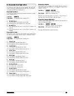
Group 03: Remote Control
There are 5 remote controlled outputs, which can be assigned to
an output:
No
Type & Description
0301 Remote
Control
1
This output type is switched on and off via the
AlcoUDL
software or via a touch tone telephone.
0302-
0305
Remote Control 2 - 5
As Remote Control 1.
Group 04: Link Control
There are 99 Link controlled outputs, which can be assigned to an
output:
No
Type & Description
0401
Link Control 01
This output type is controlled by a combination of linked
inputs.
0402-
0499
Link Control 02 - 99
As Link Control 01.
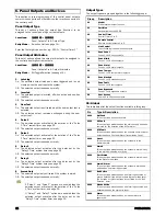
To create a link controlled output you must assign link inputs to
the Link Control. The available inputs are:
f
Zone Links
f
Control Timer Links
f
System Links
f
User Link
The inputs can be assigned to the Link Control to perform either a
logical “OR” function or a logical “AND” function. The logic
function is controlled by the link input number:
001 - 099: Logical “OR” Link inputs.
101 - 199: Logical “AND” Link inputs.
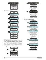
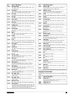
Link Control Example 1
In the first example we will setup “Link Control 01” so that it
activates when zone 1 “OR” zone 2 “OR” zone 3 is active “OR”
user 02 is entered. The figure below show the logic diagram for
this:
Í
Ë
Ì
Ê
Link Control 01
Logic “1”
Logic “1”
Logic “1”
Logic “1”
The four switches represent the link inputs and programmed as
follows:
Location 1901: Zone 01 Link = 001 (Link Control 01 “OR”).
Location 1902: Zone 02 Link = 001 (Link Control 01 “OR”).
Location 1903: Zone 03 Link = 001 (Link Control 01 “OR”).
Location 8502: User 02 Link = 001 (Link Control 01 “OR”).
As the figure above shows the Link Control 01 will be active (logic
1) when any of the input links are closed (active). Now that Link
Control 01 is configured it can be assigned to a panel output.
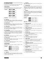
Link Control Example 2
In this example we will setup “Link Control 02” so that it activates
when zone 4 “AND” zone 5 are active “AND” when the system is
armed. The figure below shows the logic diagram for this:
Ë
Ì
Ê
Logic “1”
Link Control 02
The three switches represent the link inputs and are programmed
as follows:
Location 1904: Zone 04 Link = 102 (Link Control 02 “AND”).
Location 1905: Zone 05 Link = 102 (Link Control 02 “AND”).
Location 3904: System Armed Link = 102 (Link Control 02
“AND”).
As the figure above shows, the Link Control 02 will be active (logic
1) only when ALL of the input links are closed (active).
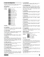
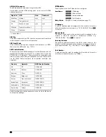
Link Control Example 3
In this example we will setup “Link Control 03” so that it activates
when zone 10 “AND” Control Timer 1 is on “OR” when the system
is in exit mode “OR” when an intruder alarm occurs. The figure
below show the logic diagram for this:
Ì
Í
Ê
Link Control 03
Logic “1”
Logic “1”
Logic “1”
Ë
The four switches represent the link inputs and programmed as
follows:
Location 1910: Zone 10 Link = 103 (Link Control 03 “AND”).
Location 3541: Control Timer 1 Link = 103 (Link Control 03
“AND”).
Location 3935: System Exit Link = 003 (Link Control 03 “OR”).
Location 3909: System Intruder Alarm Link = 003 (Link
Control 03 “OR”).
As the figure above shows the Link Control 03 will be active (logic
1) only when link input 1 and 2 are closed (active) or when either
link inputs 3 and 4 are closed (active).
Group 10: Zone Count
The zone activity count threshold of each zone can be assigned to
an output:
No
Type & Description
1001 Zone
01
Count
This output type activates when zone 01 activity count
reaches the threshold set by the “Zone Warning” counter.
See page 23.
1002-
1018
Zone 02 - 18 Count
As Zone 01 Count.
Содержание EC-P8
Страница 1: ...EC P8 8 18 Zone Intruder Alarm System Installation Manual...
Страница 4: ...4 P0031 LI 02 01 1 System Overview System Configuration...
Страница 45: ...P0031 LI 02 01 45 Notes...
Страница 46: ...46 P0031 LI 02 01 Notes...
Страница 47: ...P0031 LI 02 01 47 Notes...
Страница 48: ...Technical Support Email support zetaalarmsystems com...


