background image

a measurable difference!

®

Gold Series

Thermal Dispersion Airflow Measurement Technology

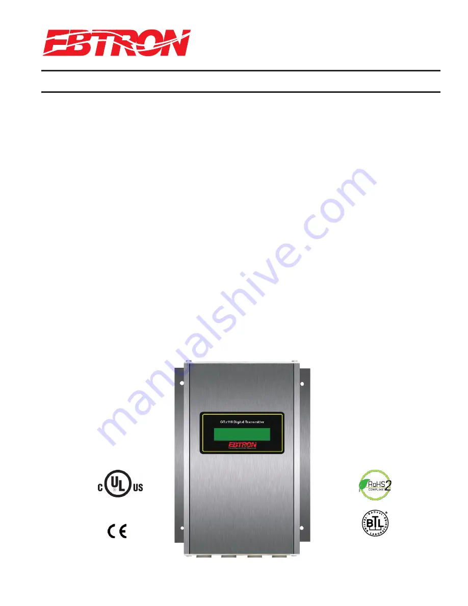
Model

GTx116

Technical Manual 

Advantage III

Gold 

Series by Ebtron

Installation, Operation and Maintenance Technical Manual

GTx116

“Plug & Play” Transmitters

Combination RS-485 and Dual Analog output model: GTC116

Combination Ethernet and Dual Analog output model: GTM116

LonWorks

®

output model: GTL116

Data Logger output model: GTD116

Document Name: TM_GTx116_R9A1

EBTRON

, Inc.  1663 Hwy. 701 S., Loris SC 29569 

• 

Toll Free: 800.2

EBTRON

(232.8766) 

• 

Fax: 843.756.1838 

• 

Internet: 

EBTRON

.com

TM_G

Tx1

1

6_R9A1

LISTED

European Union

Shipments

Part Number: 930-0000

Models GTC116 and GTM116


BACnet is a registered trademark of ASHRAE. ASHRAE does not endorse, approve or test
products for compliance with ASHRAE standards. Compliance of listed products to the
requirements of ASHRAE Standard 135 is the responsibility of BACnet International (BI).
BTL is a registered trademark of BI.

Models GTC116 and GTE116

Содержание GTx116

Страница 1: ...6 Data Logger output model GTD116 Document Name TM_GTx116_R9A1 EBTRON Inc 1663 Hwy 701 S Loris SC 29569 Toll Free 800 2EBTRON 232 8766 Fax 843 756 1838 Internet EBTRON com TM_GTx116_R9A1 LISTED Europe...

Страница 2: ...nsert latest changed pages in bold text remove and dispose of superseded pages Total number of pages in this manual is 44 Page No Revision Description of Change Date 1 2 R9A Updated revision to R9A 05...

Страница 3: ...116 Resetting Communications Options to Factory Default Values 18 GTM116 TRANSMITTER SETUP FOR ETHERNET NETWORK OPERATION 19 GTM116 Selecting Static or Dynamic IP Settings 19 GTM116 Setting Ethernet T...

Страница 4: ...nnectivity Options 6 Table 2 GTx116 Power Transformer Selection Guide 8 Table 3 Standard IP and SI Menu Units Abbreviations 12 Table 4 Factory Default Menu Settings 13 Table 5 GTx116 Alarm Types and N...

Страница 5: ...Independent airflow and temperature output Analog output signals and network protocols avail able for interface with virtually all modern building automation systems Maximum Sensing Points 16 16 airfl...

Страница 6: ...4 20mA and RS 485 BACnet Modbus Transmitter Type Type A ORDERING GUIDE GTx116 TRANSMITTER Figure 3 GTx116 Transmitter Ordering Guide Table 1 GTx116 Connectivity Options Figure 2 GTx116 Transmitter Fea...

Страница 7: ...from all of the sensor probes reach the receptacles on the bottom of the transmitter enclosure Figure 4 GTx116 Transmitter Mechanical Detail Drawing GTx116 Mechanical Dimensions 2 IF UNIT HAS 2 PROBE...

Страница 8: ...e isolated from the power supply it is not necessary to pro vide an isolated secondary not grounded power source Multiple GTx116 transmitters wired to a single transformer must be wired in phase L1 to...

Страница 9: ...ug ribs towards receptacle when removing Forcing the cable plug in or out of the receptacle will damage the connectors and void warranty If traverse data is desired probes should be installed and conn...

Страница 10: ...al 1 and temperature airflow alarm or trouble alarm output is at terminal 2 GTC116 RS 485 NETWORK WIRING CONNECTIONS Refer to Figure 8 and the following paragraph for network wiring considerations RS...

Страница 11: ...ination Analog RS 485 Output Card P N 800 1825 ACTIVITY TRAFFIC LINK D4 D3 D2 ETHERNET 10 100 VDC mA S1 S2 F1 F2 ESC ENTER CONTRAST REPLACE WITH 1 5 AMP FAST ACTING ONLY OUTPUT 1 2 COM POWER 24VAC IN...

Страница 12: ...ts of measure abbreviations used in the menus is shown in Table 3 Check the physical installation power connections and model specific signal wiring prior to turning the power switch to the on positio...

Страница 13: ...operates in conjuction with TOL value 0 0 TOL Alarm range tolerance value When AO2 ASGN ALARM this setting establishes the alarm range relative to the S SETPNT value 10 10 NO FAULT Sets the AO2 norma...

Страница 14: ...he LCD dis play units will not affect the analog output signal Converting the Analog Output Signal from FPM to CFM The GTx116 transmitter is shipped from the factory with analog output OUTPUT 1 set to...

Страница 15: ...able end of the probe is defined as sensor 1 when viewing individual sensor data Refer to Figure 10 below for additional detail Note that if only average data is desired the mounting position of the p...

Страница 16: ...below the SETPNT value The defined level is equal to the SETPNT value minus the calculated value of TOL value SETPNT value Once active the alarm can be cleared when the average airflow rises above the...

Страница 17: ...S GTC GTM116 ANALOG OUTPUT TYPE SELECTION AND SETUP The analog output signal type at OUT1 airflow and OUT2 temperature alarm can be set for mA or VDC output by set ting switches SW1 SW2 Figure 8 and b...

Страница 18: ...ected by setting the TERMINATION DIP switch SW3 Figure 8 on the Combination board GTC116 Setting RS 485 Network Protocol Transmitter protocol can be set for BACnet MS TP or MODBUS as shown in the NETW...

Страница 19: ...ired For manual device configuration of the GTM116 set menu item DHCP OFF factory default as shown in Appendix B When manually changing IP settings DHCP OFF the display will blink the 3 digit address...

Страница 20: ...ber can also be changed by writing to the Device Object s Object Identifier Property over the network GTM116 Resetting Communications Options to Factory Default Values Communications options can be re...

Страница 21: ...04 float F Average Temperature 20 to 160 4 30005 word Number of Inserts 0 to 16 4 30007 word Alarm Status 0 No alarm 1 High Alarm 2 Low Alarm 3 Both 4 30008 word Connector C1 Sensors 0 to 8 4 30009 wo...

Страница 22: ...t is isolated from the main power input Connect the LonWorks cable at the OUTPUT terminal block as follows OUTPUT TERMINAL SIGNAL DESCRIPTION 1 NET 2 NET COM COMMON NOT USED Figure 11 GTL116 LonWorks...

Страница 23: ...n of various parameters within a device These are intended to control the basic operation of a device All network variables are defined in terms of SNVT_xxx SNVT is an acronym for Standard Network Var...

Страница 24: ...nge in velocity that will cause an update of flow and velocity to the net work The change is only checked for in velocity and when the minimum is reached updates will occur for nvoVel nvoFlow and nvoF...

Страница 25: ...ates This configuration property sets the minimum time to elapse before an update to the network for pressure may be sent This configuration property takes priority over maxSendTime and sndDelta nvoPr...

Страница 26: ...n property takes priority over maxSendTime and minDeltaTemp GTL116 DEFAULT DELTA VALUES The default Delta values determine when updates are sent from the transmitter to the network The Delta values ar...

Страница 27: ...by EBTRON Performing duct traverses with permanently mounted EBTRON airflow probes eliminates the requirement to make additional sampling holes in the duct and reduces the need to carry around the jo...

Страница 28: ...Windows Mobile operating system Data can also be returned over BACnet or Modbus when probes are connect ed to a GTC116 GTM116 transmitter Real Time Duct Traverses Using EB Link Simply slide the GTx116...

Страница 29: ...e adjusted Ensure that the reference device and technique used to determine the airflow rate in the field are suitable for such measurement Select a location that is acceptable for the device being us...

Страница 30: ...ngs to be set on the transmitter Measurement units can be in either FPM or CFM but they need to be the same between transmitter and refer ence When using FPM ensure that area for both measurements is...

Страница 31: ...ng with the control sequence of operations is recommended to help us diag nose problems Fax the information to 843 756 1838 before you call and have it available when speaking with the Customer Servic...

Страница 32: ...ON but not flashing The microprocessor is not running Reset 24VAC power by moving the power switch from the ON to OFF position and then back to the ON posi tion The green Transmitter Status LED D3 on...

Страница 33: ...back ON Network signal wiring is not properly connected to the GTC116 transmitter or the host controls Verify that the network signal wires from the host con trols are connected to the proper termina...

Страница 34: ...s unable to communicate with the GTL116 transmitter Output card is not securely mounted on main circuit board Turn the transmitter power OFF and press the output card firmly onto main circuit board Tu...

Страница 35: ...OR ALARM OUTPUT SIGNAL ANALOG BAS CONTROL INTERFACE OUT 2 can be set for analog Temperature Alarm or Trouble output Alarm output can be set as active high or active low NOTES 1 OUTPUT 2 CAN BE SET AS...

Страница 36: ...MITTER INSTALLATIONS WITH A COMMON 24VAC SOURCE WIRE 24 VAC POWER IN PHASE TO THE SAME TERMINALS ON ALL TRANSMITTERS e g L1 to L1 L2 to L2 TRANSFORMER 24 VAC 50 60 HZ SEE NOTE 3 LINE IN 24 VAC USE LON...

Страница 37: ...easurable difference APPENDIX B GTx116 SETUP MENUS 37 EBTRON Inc 1663 Hwy 701 S Loris SC 29569 Toll Free 800 2EBTRON 232 8766 Fax 843 756 1838 Internet EBTRON com GOLD SERIES GTX116 TRANSMITTER a meas...

Страница 38: ...Standard units SFPM SCFM AIRFLOW ACT Custom LCD Flow Text Blinking prompt at position of the selected character Character is selected using the up and down arrows and then ENTER to accept and move cu...

Страница 39: ...gs part 4 AO2 FS 160 AO1 FS 5000 SET AO1 FS AO1 FS 5000 AO2 ASGN TRBL AO1 INTG 30 SET AO1 INTG AO1 INTG 30 SET AO1 RNGE Set analog output range VDC for AO1 AO1 RNGE 0 10 AO1 RNGE 0 5 AO1 UM AFPM SET A...

Страница 40: ...00 001 NETBAUD 76800 SET NETBAUD NETBAUD 76800 PARITY EVEN SET PARITY PARITY EVEN NETOUT BACNET SET NETOUT NETOUT BACNET Set network protocol type O O NETWORK SET IP SET NETADDRESS NETWORK IP 10 0 0 1...

Страница 41: ...AIRFLOW setting above LO ALRM ON SET LO ALRM Enable disable HI alarm LO ALRM OFF Enable disable LO alarm HI ALRM OFF SET HI ALRM HI ALRM OFF LO ALRM OFF O O When ZERO OFF YES this setting is used to...

Страница 42: ...ADJ ON GAIN 1 000 SET GAIN GAIN 1 000 SET FLOW ADJ FLOW ADJ OFF OFF 0 OF FLOWS 2 SET OF FLOWS OF FLOWS 1 Set OUT2 to of full scale analog output Start field adjust wizard and enter number of integrati...

Страница 43: ...currently displayed TRBL alarm To disable all trouble codes see SETUP DISPLAY LCD TRBL For sensors 1 to 9 A to G number of sensors dependant on sensor type For sensors 1 to 9 A to G number of sensors...

Страница 44: ...a measurable difference EBTRON Inc 1663 Hwy 701 S Loris SC 29569 Toll Free 800 2EBTRON 232 8766 Fax 843 756 1838 Internet EBTRON com...

Отзывы: